Page 22
ePump
™
Series Pumps, Installation and Operation Manual
6.2.4 Variable Speed Drive Electronics
Replacement
NOTE The Variable Speed Drive Electronics Unit and
the motor are separate pieces of equipment and
can be replaced independently of each other.
WARNING
To ensure continued safety and reliable operation,
Zodiac Pool Systems, Inc. requires that you replace
the Variable Speed Drive Electronics Unit with
a unit
that has the identical HP rating and service factor
(Zodiac Pool Systems, Inc. approved unit only).
1. Turn off the electrical power to the pump motor
using your controller. Switch off the circuit
breaker to the pump motor.
WARNING
ELECTRICAL SHOCK HAZARD
Turn off all switches and the main breaker in
the ePump electrical circuit before starting the
procedure. Wait five (5) minutes after power is
disconnected before opening motor.
Do not proceed
until the LED on top of the Drive Electronics is
completely off. Failure to comply may cause a shock
hazard, resulting in severe personal injury or death.
NOTE For instructions on operating the controller, refer
to your controller manual: ePump Controller
Owner’s Manual, H0311200, AquaLink
®
RS
Owner’s Manual, 6593, or AquaLink
®
PDA
Owner’s Manual, H0572300.
2. Remove the junction box lid and disconnect
the three (3) high voltage wires and the four (4)
communication wires.
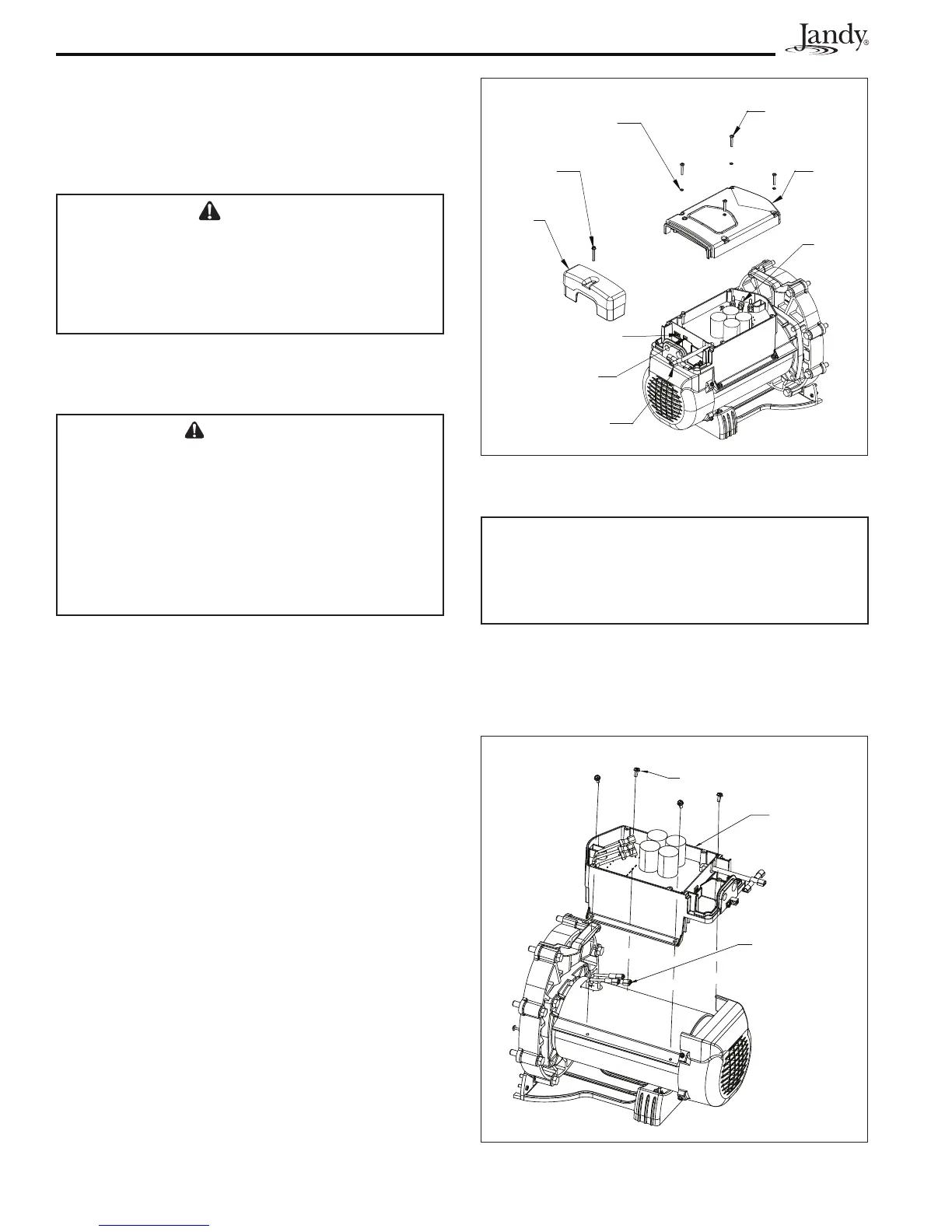
3. Remove the four (4) screws and o-rings on the
main cover and remove the main cover. See
Figure 14.
4. Unplug the three-wire harness from the board. See
Figure 15.
5. Remove the four (4) screws that secure the
electronics enclosure to the motor. See Figure 15.
6. Remove the electronics enclosure and mount
the new electronics enclosure using the four (4)
screws that secure it to the motor. See Figure 15.
7. Plug the three-wire harness into the connector on
the board.
8. Replace the main cover using the four (4)screws
that secure it in place. See Figure 14.
9. Reconnect the three (3) high voltage wires and the
four (4) communication wires.
CAUTION
IMPORTANT! To prevent potential damage to the
ePump, AquaLink
®
RS, or AquaLink
®
PDA, set the dip
switches to the same settings used in the previous
Variable Drive Electronics Unit.
10. Set the dip switches to the same settings set in the
previous Variable Speed Drive Electronics Unit.
See Section 3.3, ePump Dipswitch Settings.
11. Re-install the junction box lid.
Four Main
Cover Screws
Main
Cover
Three
Wires to
Board
Four
Communication
Wires
Three High
Voltage Wires
Junction
Box Lid
Junction Box
Lid Screw
Four O-rings
Dip
Switches
Figure 14. Remove Main Cover for Variable Speed
Drive Electronics Unit
Three (3) Wires
Connect to
Board
Electronics
Enclosure
Four (4) Screws for
Electronics Enclosure
Figure 15. Remove Variable Speed Drive
Electronics Enclosure