Page 12 ENGLISH
Jandy
®
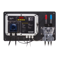
TruDose
TM
Chemical Controller
|
Installation & Operation Manual
Section 3.
Installation
3.1 Setup
1. Turn o all peripheral equipment such as heaters
and pumps.
2. Relieve pressure from the ltration system.
3.2 Tools
• Cordless drill
• 1/4" NPT Tap (provided)
• 7/16" drill bit
• Masonry drill bit and anchors or other appropriate
fasteners.
• 13/16" wrench or channel-lock pliers
• Water-tight outlet cover for outdoor installations
3.3 Power Supply
• The TruDose Chemical Controller needs to be
connected to a GFCI protected watertight outdoor
outlet.
• Do not use extension cords.
• The power supply must be installed at least 1 ft
(30cm) above the ground surface. Ensure the power
supply is protected from direct water exposure from
sprinklers, water runo from rooftops and drainage.
ATTENTION
The controller must be powered only with the provided
power supply, and connected to a dedicated GFCI
protected electrical circuit, Class A GFCI in Canada. No
other equipment, lights, appliances, or outlets may be
connected to the controller circuit.
3.4 Controller Installation
3.4.1 Location
• Wall area with easy access
• At least 5 feet (1.5 m) horizontally from the edge of
the pool and/or spa. In Canada, at least 3 meters (10
feet) horizontally from the edge of the pool and/or
spa.
• Within 15 feet of GFCI power source
CAUTION
In order to avoid premature failure or damage to the
controller, protect the controller from direct water exposure
fromsprinklers,waterrunofromrooftopsanddrainage,
etc. Failure to comply may cause controller failure, and
may void the warranty.
• The TruDose Controller must be installed at least
2 feet (0.6 m) vertically o the ground surface.
Ensure the controller is protected from direct water
exposure from sprinklers, water runo from rooftops
and drainage.
3.4.2 Mounting
NOTE: The controller and flow cell are factory
mounted to the ABS board for your
convenience.
1. Securely mount ABS mounting board with the
chemical controller and ow cell on the wall.
2. Drill a 7/16" hole and tap a 1/4" NPT port to a
location downstream from the lter and upstream
from any heater or chemical introduction point.
Install a tubing connector (included) and 3/8" ex
tubing to be connected to the left side ow cell port
containing the ow switch. The in-line lter will
also be installed in this line in an easily-accessible
location.
NOTE: Verify that the in-line filter is installed with
directional arrows pointing in the direction of the
flow (towards flow cell).
3. Drill a 7/16" hole and tap a 1/4" NPT port to a
location that is subject to vacuum or reduced
pressure. Install a tubing connector (included) and
3/8" ex tubing to be connected to the right side
ow cell port.
NOTE:
We recommend that this tubing connector be
installed into the drain hole on the suction side
of the pump for best performance.
4. Cut 3"-6" length of 3/8" ex tubing and insert into
the ow cell's sample stream port (center).
3.5 pH and ORP Sensors
Installation
NOTE: Carefully unpack the pH and ORP sensors and
set aside in a clear area until ready to install into
the flow cell.
1. Verify that the controller power is o.
2. Carefully remove the plastic protective container
from the sensors and store in a separate location for
future re-use.
3. Loosen (do not remove) the top nut of the
compression ttings at the top of the ow cell and
carefully slide the glass end of each sensor (pH
and ORP) into the compression ttings. Ensure
that the tip is submerged into the water to within
1/2" from the bottom of the ow cell. Hand tighten
each nut tting. Do not use any tools to tighten the
compression ttings.
4. Electrical Connections
• Verify that the controller is o.
• Connect the pH sensor connector (blue) to the left
BNC connector on the bottom of the controller.
• Connect the ORP sensor (red) to the right BNC
connector on the bottom of the controller.
• Plug power supply into the GFCI protected outlet
(outdoor installations should have weather proof
enclosures installed).
NOTE: Continue to monitor free chlorine with manual
testing to ensure proper sanitation levels.