Page 4
ENGLISH Jandy
®
WaterColors RGBW LED Lights | Installation & Operation Manual
National Electrical Code
®
(NEC
®
) requires bonding
of the Pool Water. Where none of the bonded
pool equipment, structures, or parts are in direct
connection with the pool water; the pool water shall
be in direct contact with an approved corrosion-
resistant conductive surface that exposes not less
than 5800mm² (9 in²) of the surface area to the pool
water at all times. The conductive surface shall be
located where it is not exposed to physical damage
or dislodgement during usual pool activities, and
it shall be bonded in accordance with the bonding
requirements of NEC Article 680. Refer to locally
enforced codes for any additional pool and spa
bonding requirements.
NOTE: To be certain that the pool’s electrical system meets
all applicable requirements, the electrician should also
consult the local building department.
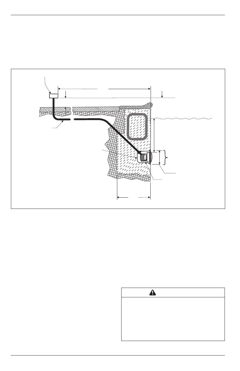
8" min. Junction Box or Low
Voltage Transformer*, to the max
water level of the pool.
18" min. to top of lens
48"
min.
Rigid Conduit
4" min.
To GFCI, Circuit Breaker and Power Source.
Concrete must be cut back
around niche to allow for a
compacted plaster seal.
11.50"
16"
Coil 4 ft. of light cable
around fixture.
#8 AWG Ground
Connector bonding
is located at rear of
niche.
* Or per junction box and/or transformer
manufacturer's instructions.
Figure 1. Jandy Digital Color Light Installation
Use only approved wet niches (see following note) to
ensure a safe and proper installation.
NOTE: Jandy lights are ETL listed for installation with
only
the
following manufacturer’s wet niche fixtures:
Large Niche Model Numbers:
Jandy: PLNICLRG, PLNICVFLRG, WT000002,
SSNICLRG1R, SSNICLRG1S
Pentair
®
: 620004, 78210200 thru 700, 78210401
Hayward
®
DuraNiche: SP0600U
Small Niche Model Numbers:
Jandy: PLNICSM, SSNICSM,
Pentair: 79206600
2.2 Installing the Light Fixture
NOTE: Perform these steps
only
after the electrical system
requirements are met.
1. Feed cord through conduit to junction box, leaving
at least four (4) feet of cord at the light fixture to coil
into the base of the light niche, see
Figure 1
. The
four (4) feet of cord allows the light to be serviced
after the pool is filled with water.
2. Cut the cord at the junction box, leaving at least six
(6) inches of cord to make connections.
3. Strip six (6) inches of the outer cord jacket to
expose the three insulated wires.
Be careful not to
damage the insulation on the three (3) inner wires.
4. Install strain relief over cord jacket and connect all
three (3) wires to the corresponding circuit wires in
the junction box. Install the junction box cover.
5. Coil the 4-foot length of cord around the fixture or
into the base of the pool niche, and place the light
assembly into the niche.
6. Engage the retainer tab on the bottom of the face
ring, then pivot the top of the fixture inward and
tighten the special pilot screw.
WARNING
Use only the special pilot screw provided with this
underwater light. This screw mounts and electrically
grounds the housing securely to the mounting ring
and wet niche. Failure to use the screw provided could
create an electrical hazard, which could result in death
or serious injury to pool or spa users, installers or others
due to electrical shock.


 To Next Page