CTI-CRYOGENICS
HELIX TECHNOLOGY CORPORATION
A regenerator is a reversing-flow
heat exchanger through which the
helium passes alternatively in
either direction. It is packed with a
material of high surface area, high
specific heat, and low thermal con-
ductivity, that will readily accept
heat from the helium (if the he-
lium's temperature is higher) and
give up this heat to the helium (if
the helium's temperature is lower).
In steady-state operation, a
system of this type exhibits the
characteristic temperature profile of
Figure 3. The steps of the cycle are
as follows:
Figure 3 Temperature Profile of a
Single-Stage Cryodyne
Refrigerator
a.
With the piston at the bottom of
its stroke, compressed gas enters
through valve A at room
temperature (1).
b.
As the piston rises, the gas
passes through the regenerator.
The matrix absorbs heat from
the gas (warming from 3 to 4),
and the gas cools.
c.
Still at inlet pressure, the cooled
gas fills the space beneath the
piston. The gas temperature at
this point (5) is about the same
as that of the load.
d.
Valve A closes and exhaust
valve B opens, allowing the gas
to expand and cool further as it
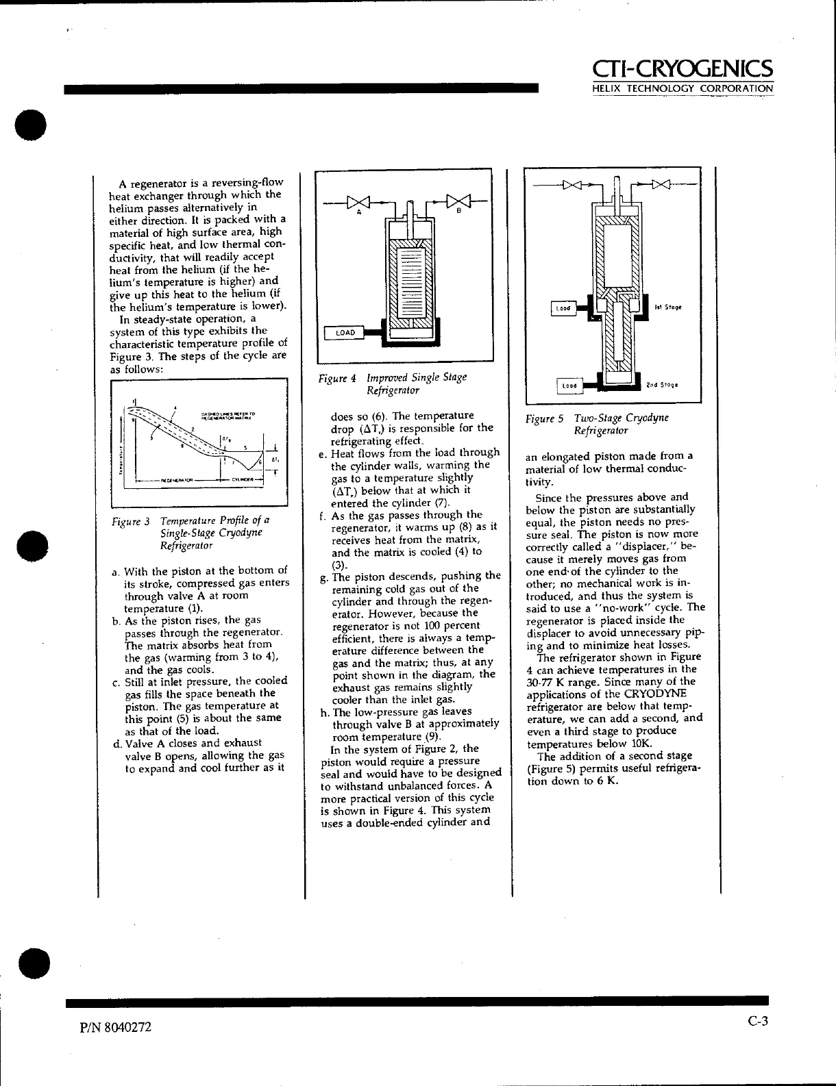
Figure 4 Improved Single Stage
Refrigerator
does so (6). The temperature
drop (ST,) is responsible for the
refrigerating effect.
e.
Heat flows from the load through
the cylinder walls, warming the
gas to a temperature slightly
(ST,) below that at which it
entered the cylinder (7).
f.
As the gas passes through the
regenerator, it warms up (8) as it
receives heat from the matrix,
and the matrix is cooled (4) to
(3).
g.
The piston descends, pushing the
remaining cold gas out of the
cylinder and through the regen-
erator. However, because the
regenerator is not 100 percent
efficient, there is always a temp-
erature difference between the
gas and the matrix; thus, at any
point shown in the diagram, the
exhaust gas remains slightly
cooler than the inlet gas.
h.
The low-pressure gas leaves
through valve B at approximately
room temperature (9).
In the system of Figure 2, the
piston would require a pressure
seal and would have to be designed
to withstand unbalanced forces. A
more practical version of this cycle
is shown in Figure 4. This system
uses a double-ended cylinder and
Figure 5 Two-Stage Cryodyne
Refrigerator
an elongated piston made from a
material of low thermal conduc-
tivity.
Since the pressures above and
below the piston are substantially
equal, the piston needs no pres-
sure seal. The piston is now more
correctly called a "displacer," be-
cause it merely moves gas from
one end- of the cylinder to the
other; no mechanical work is in-
troduced, and thus the system is
said to use a "no-work" cycle. The
regenerator is placed inside the
displacer to avoid unnecessary pip-
ing and to minimize heat losses.
The refrigerator shown in Figure
4 can achieve temperatures in the
30-77 K range. Since many of the
applications of the CRYODYNE
refrigerator are below that temp-
erature, we can add a second, and
even a third stage to produce
temperatures below 10K.
The addition of a second stage
(Figure 5) permits useful refrigera-
tion down to 6 K.
P/N 8040272
C-3
 Loading...