Do you have a question about the janitza UMG 512-Pro and is the answer not in the manual?
Compliance requirements for safe operation and product features.
Guidance on matching device to manual and keeping documents.
Procedures for returning defective devices and proper disposal.
Details on warning notices, symbols, and hazard level indicators.
Explanation of DANGER, WARNING, CAUTION, ATTENTION, INFORMATION levels.
Identifies risks associated with electrical voltage and improper handling.
Safety guidelines for handling current transformers and measurement devices.
Overview of the device's design, capabilities, and intended applications.
Specifies the intended industrial sector and installation environments.
Details general and measurement-specific technical features and capabilities.
Describes how to program the device and retrieve measured values.
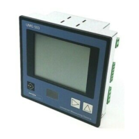
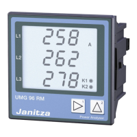
Description of the front panel layout, display, and function buttons.
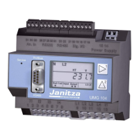
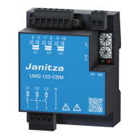
Identification of connection terminals and components on the rear panel.
Guidance on suitable locations and grounding requirements for installation.
Instructions on how to fasten the device to a switchboard using clips.
Describes suitability and connection for three-phase, 3-conductor systems.
Describes suitability and connection for three-phase, 4-conductor systems.
Details various methods for connecting the device to a PC for configuration.
Instructions for connecting the device's power supply and safety precautions.
Guidelines for connecting voltage measurement inputs and safety considerations.
Instructions for connecting current transformers and safety warnings.
Recommendations for proper cable shielding and grounding for interfaces.
Details on the RS-485 interface, protocol, and termination resistors.
Information on connecting and configuring the Profibus interface.
Configuration options for the Ethernet interface, including IP settings.
Description of the two digital inputs, their voltage requirements, and connection.
Description of the two digital outputs, isolation, and use as pulse outputs.
Details the function of each of the six device buttons.
Overview of the initial display after power restoration, showing key values.
Instructions on how to navigate and select different measuring displays.
Configuring Ethernet (TCP/IP) and Fieldbus (RS-485) settings.
Settings for transformers, transients, events, voltage, frequency, flicker, sensors.
Accessing and changing system settings like password, reset, and firmware version.
Steps to apply the supply voltage and initial checks.
Procedure for connecting voltage measurements and safety considerations.
How the device determines or requires mains frequency for measurements.
Instructions for connecting current measurements and verifying readings.
Accessing and visualizing current and historical measurement data.
Retrieving power quality status according to EN 50160 and IEC 61000-2-4.
Information on installing additional applications to enhance device functionality.
Procedures for device repairs and calibration, performed by the manufacturer.
Steps to update the device firmware using GridVis® software.
Information on the internal clock battery, its life expectancy, and replacement.
Detailed specifications for the device's power supply options.
Technical specifications for voltage and current measurement capabilities.
Specifications for digital inputs and outputs, including connection capacity.
Technical details for RS-485, Profibus, and Ethernet interfaces.
Diagram showing the structure of the device configuration menus.
Diagram illustrating the navigation flow between different measuring displays.
| Device Type | Power quality analyzer |
|---|---|
| Power Measurement | Active, reactive, apparent power |
| Operating Temperature | -10 °C to +55 °C |
| Frequency Measurement | 45 - 65 Hz |
| Energy Measurement | Active, reactive, apparent energy |
| Communication Interfaces | Ethernet, RS485, USB |
| Protocols | Modbus TCP, Modbus RTU |
| Display | Graphical LCD |
| Memory | Internal memory for data storage |
| Power Supply | 85 - 265 V AC |
| Dimensions | 96 x 96 mm |
| Accuracy | 0.5 % |
| Measurement Category | CAT III 600V, CAT IV 300V |
| Current Measurement | Via Current Transformer (1 A or 5 A) |