Do you have a question about the janitza UMG 801 and is the answer not in the manual?
Legal disclaimers regarding device operation and copyright notice for the manual.
Information on technical updates and the scope of this user manual.
Guidelines for the proper disposal of defective devices and components.
Explanation of warning symbols and safety information presentation.
Definition and explanation of different hazard warning levels.
General product safety guidelines and warnings for safe operation.
Identification of risks and dangers associated with handling the device.
Requirements and qualifications for personnel working on electrical devices.
Specific safety guidelines for handling and connecting current transformers.
Safety information for devices with residual current measurement functionality.
Safety instructions for handling and replacing batteries.
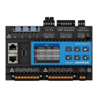
Detailed description of the UMG 801's features and capabilities.
Procedures for inspecting delivered devices for completeness and condition.
Information on the device's intended applications and operating environments.
Overview of the device's technical performance and specifications.
Information on the device's compliance with EU and UKCA regulations.
Information on the device's compliance with FCC regulations.
List of items included in the product delivery.
List of available optional accessories for the device.
Explanation of the device's measurement techniques and principles.
Information and usage guidelines for current and voltage transformers.
Overview of the device's operating modes and interaction methods.
Accessing and using the device's integrated web server homepage.
Information on the GridVis network analysis and programming software.
Overview of functions configurable directly on the device via buttons.
Overview of the device's communication interfaces and protocols.
Table detailing measured voltage-related values and their parameters.
Table detailing measured current-related values and their parameters.
Description and illustration of the device's front panel and display elements.
Illustrations showing the side and bottom views of the device.
Explanation of the information presented on the device's rating plate.
Guidance on selecting an installation location and associated safety precautions.
Instructions for installing and connecting the bus connector.
Step-by-step guide for mounting the device on a DIN rail.
Suitable nominal voltages and grid types for installation.
Guidance on selecting and installing appropriate circuit breakers.
Instructions for connecting the device's supply voltage.
Overview of voltage measurement capabilities and connection options.
How the device detects and utilizes the mains frequency.
Diagrams illustrating different connection variants for voltage measurement.
Explanation of how the device performs current measurements.
Diagrams showing different connection variants for current measurement.
Procedure for performing summation current measurements.
Instructions for connecting an ammeter in series for current measurement.
Description of the multifunction channels and their possible uses.
Overview of the residual current measurement functionality.
Information on current direction handling for residual current transformers.
An example illustrating the use of a residual current transformer.
Important details regarding the residual current measurement inputs.
Illustrative connection examples for residual current measurement.
Connection example for residual current monitoring.
Methods for setting and calculating residual current limit values.
Configuration of a fixed, constant limit value for residual current monitoring.
Calculation of limit values based on a reference value and scaling factor.
Calculation of limit values based on predefined steps and thresholds.
Example illustrating events when residual current limit values are exceeded.
Activating cable break detection for residual current monitoring.
Instructions and guidelines for temperature measurement using the device.
Overview of the functions and capabilities of the Ethernet interfaces.
Configuration option for connecting devices in a switched mode network.
Configuration option for connecting to two different networks (dedicated mode).
Explanation of the status indicators (LEDs) for the Ethernet interfaces.
Common methods for connecting the device to a PC for communication.
Details on the RS-485 serial interface and its communication protocol.
Guidelines for proper shielding of interface cables.
Information on using termination resistors for RS-485 bus segments.
Description of bus structure, device addressing, and segment limitations.
Details on the proprietary JanBus interface for module connection.
Description of the device's 4 digital inputs and their signal recognition.
Description of the device's 4 digital outputs and their functionalities.
Description of the device's passive analog output capabilities.
Overview of the device's controls, display, and function buttons.
Description of the device's main measured value display screen.
Explanation of how to navigate through the device's menu system.
Instructions for setting and managing the device's PIN for security.
A summary of the various menu displays available on the device.
Settings for Ethernet interfaces and Fieldbus (RS-485) communication.
Configuration of transformer ratios and display parameters.
Configuration options for system-level settings like PIN, Time, Date, and Reset.
Accessing the diagnostics menu for module identification.
How to navigate and access the main configuration window.
Detailed steps for configuring the device's Ethernet (TCP/IP) settings.
Steps for configuring the RS-485 interface for fieldbus communication.
Setting parameters like device address, baud rate, and data frame for RS-485.
Procedure for setting the ratios of connected current transformers.
Procedure for setting the ratios of connected voltage transformers.
Configuring the device for temperature measurements using multifunction channels.
List of permitted temperature sensor types compatible with the device.
Setting a temperature offset for calibration or adjustment.
Settings for device display parameters like language, standby, and brightness.
Selecting the user interface language for the device.
Configuring the time delay before the display enters standby mode.
Adjusting the brightness level of the device display.
Configuration options for system settings including PIN, Restart, Time, and Date.
Setting and managing the device's PIN for security and access control.
Procedure for restarting the device to apply changes or troubleshoot.
Configuring the device's time, time synchronization, and time zones.
Configuring the device's date settings.
Overview of device reset functions for configurations and data.
Restoring the device to its original factory default settings.
Deleting all device configuration data and restoring factory defaults.
Clearing stored minimum, maximum, and average measured values.
Deleting all current energy values stored in the meter.
Deleting all historical values, power quality data, and recordings.
Identifying connected modules and accessing diagnostic information.
Overview of power quality parameters: events and transients.
Explanation of different event types based on RMS values.
Explanation of different transient detection modes and parameters.
Details on recording lead time, lag time, and event data.
Configuring recording length (lead/lag time) for event and transient waveforms.
How the device compares RMS values to limit values for event triggering.
Time intervals for updating transient recording data points.
Configuring events and transients using the GridVis software.
Description of the device's 4 digital inputs and their configuration.
Configuring digital inputs for use as pulse counters for energy consumption.
Understanding pulse valency for measured value calculation.
Description of the device's 4 digital outputs and their configuration.
Steps for configuring digital outputs for pulse generation.
Principles and examples of analog output usage for monitoring.
Using the GridVis assistant for configuring analog outputs.
Steps for connecting the device's supply voltage during commissioning.
Procedure for connecting and verifying measured voltages.
Procedure for connecting and verifying measured currents.
How the device measures and calculates frequency.
Determining the direction of the voltage rotating field via phasor diagram.
Explanation of phasor diagrams and their representation of electrical variables.
Using phasor diagrams to check voltage and current input connections.
Verifying the correct assignment of phase conductors and current transformers.
Steps to verify the accuracy of power measurements.
General checks for correct measurement input connections.
Verifying individual phase power measurements for accuracy.
Checking the accuracy of summation power measurements.
Functionality and configuration of the drag indicator for average values.
Methods for synchronizing the drag indicator calculation periods.
Viewing drag indicator values on the measurement device display.
Procedure for resetting drag indicator values.
Explanation of how the device calculates average values.
Calculation and characteristics of gridded average values.
Calculation and characteristics of moving average values.
Configuring averaging methods and intervals in GridVis software.
Displays for the home screen and phasor diagrams.
Displays for voltage, LL, LN, and THD-U values.
Displays for current, THD-I values, and their averages.
Displays for power summary and active power values.
Displays for reactive and apparent power values.
Displays for power factor and active energy values.
Displays for reactive and apparent energy values.
Viewing drag indicator values for current, power, and apparent power.
Viewing drag indicator values for basic device 5-8.
Displays for current, temperature, and RCM overview.
Displays for RCM bar charts and residual current history.
Displays for the status of digital inputs and outputs.
Information on module identification and basic device system details.
The initial start page of the device's web homepage.
Steps for logging into the device homepage using username and password.
Instructions for changing the login password via the Settings menu.
Accessing the menu for viewing measured values.
Detailed view of measured values including energy, harmonics, power, voltage, current.
Viewing and downloading event and transient data.
Overview of the various configuration options available in the Settings menu.
Steps for updating the device firmware via the homepage.
Configuration of the Modbus whitelist for secure device access.
Display of general device information, transformer ratios, and software versions.
Accessing and downloading the Modbus address list.
Manufacturer imprint details, including contact and registration information.
Guidelines for device repair and calibration services.
Instructions for cleaning and maintaining the device's front panel and display.
Information on contacting technical support for service inquiries.
Procedure for updating device firmware using the web homepage.
Details about the device's internal clock and battery.
Guidelines and precautions for replacing the device battery.
Explanation of the overrange error and its causes.
A table outlining common malfunctions, their causes, and remedies.
General, transport, storage, and environmental specifications.
Detailed technical specifications for voltage measurement.
Detailed technical specifications for current measurement.
Specifications for RCM, temperature measurement, digital I/O, and digital outputs.
Specifications for digital inputs and outputs.
Specifications for cable lengths and analog output.
Specifications for RS-485 and Ethernet interfaces.
Information on supported communication protocols and services.
Specifications for terminal connection capacities for various interfaces.
Electrical safety and potential isolation of device interfaces.
Electrical safety and potential isolation of multifunction channels.
Electrical safety and potential isolation of digital I/O and analog output.
Information on device parameters and the Modbus address list.
Information on how the device saves measured values and configuration data.
Illustrations showing the front, left, bottom, top, and rear views of the UMG 801.
Detailed illustration of the bus connector for module mounting.
| Power Factor Measurement | Yes |
|---|---|
| Display | Graphical LCD |
| Operating Temperature | -10°C to +55°C |
| Device Type | Power Analyzer |
| Power Measurement | Active, Reactive, Apparent Power |
| Energy Measurement | kWh, kVarh |
| Frequency Measurement | 45-65 Hz |
| Harmonics Analysis | Up to 63rd harmonic |
| Communication Interfaces | Ethernet, RS485 |
| Memory | Non-volatile memory for data logging |
| Protection Class | IP54 |
| Mounting | Panel mount |