Do you have a question about the janitza UMG 103-CBM and is the answer not in the manual?
States that compliance with informational products is required for safe operation and performance.
Outlines copyright information and restrictions on reproduction, distribution, or other use of the product.
Advises users to ensure their device matches the manual and to check for updates online.
Provides contact information for questions, suggestions, or improvements regarding the user manual.
Instructions for returning defective devices and guidelines for proper disposal of device components.
Explains the meaning and placement of warning symbols and notices throughout the documentation.
Details the different hazard levels (Danger, Warning, Caution, Attention) and their associated symbols.
Highlights safety standards, potential hazards from tampering, and the importance of reading the manual.
Warns about electrical hazards, proper disconnection, grounding, and protective measures.
Specifies that only qualified personnel should work on the device and its components.
States that unauthorized tampering or misuse voids the product warranty.
Provides safety precautions for working with current transformers to prevent injury or damage.
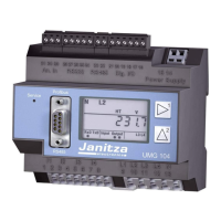
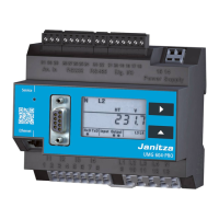
Describes the UMG 103-CBM as a compact energy analyzer suitable for building installations.
Outlines steps for inspecting the device upon receipt to ensure safe and trouble-free operation.
Specifies the device's intended applications in the industrial sector and installation requirements.
Lists general, measurement uncertainty, and measurement specifications of the UMG 103-CBM.
Refers users to the website for the EU declaration of conformity and CE marking requirements.
States compliance with FCC rules for digital devices and provides guidance on radio interference.
Lists the items included in the standard scope of delivery for the UMG 103-CBM device.
Lists available accessories such as termination resistors and interface converters.
Explains how the device continuously calculates effective values and measures true RMS values.
Advises using only current transformers for measurement purposes and avoiding protection transformers.
Details the device's operating concept including coding switches, GridVis software, and Modbus protocol.
Introduces GridVis software as a tool for configuration, readout, and analysis of measurement data.
Identifies and describes the components and controls located on the front panel of the device.
Explains the meaning of different LED indications (green, red, blinking) for device status.
Details the information found on the device's rating plate, including operational data and manufacturer info.
States that the mounting orientation of the device is arbitrary and forced ventilation is not required.
Provides safety instructions and requirements for selecting a suitable installation location for the device.
Lists suitable mains and nominal voltages for the meter, specifying ranges for different network types.
Details suitable mains and nominal voltages for three-phase four-conductor systems with a grounded neutral.
Recommends providing a suitable disconnect switch for the supply voltage for safe isolation.
Explains how the device obtains supply voltage and provides precautions for connecting it.
Describes the voltage measurement inputs and provides safety warnings for connection and use.
Discusses voltage measurement design for low-voltage networks and refers to technical data for surge voltages.
Explains the device's reliance on mains frequency for measurements and its suitability for 45-65 Hz networks.
Illustrates different connection configurations for voltage measurement in three-phase and single-phase systems.
Shows connection diagrams for current measurement via current transformers in different system configurations.
Explains how to connect an ammeter in series with the UMG for current measurement.
Describes how to correct current direction for each phase via serial interfaces without reconnecting transformers.
Details how to perform summation current measurement using two current transformers and device adjustment.
Presents multiple possibilities for connecting the device to a PC via interface converters or masters.
Describes the 3-pole RS-485 interface for Modbus RTU communication and associated safety warnings.
Provides guidelines for proper shielding of cables connected via interfaces to prevent interference.
Explains the principles of a bus structure, device addressing, and segment termination for RS-485 networks.
Specifies the requirement for termination resistors at the beginning and end of a bus segment.
Guides on configuring current and voltage transformer ratios using the GridVis software.
Explains how to set unique device addresses using rotary selector switches for RS-485 bus operation.
Details the RS-485 interface operation, Modbus functions, and transmission parameters.
Instructions for connecting and checking measured and supply voltages, including safety precautions.
Steps for connecting current transformers and comparing measured current with device readings.
Explains how to check the direction of the voltage rotating field using the GridVis software.
Describes phasor diagrams and their representation of voltage and current phase shifts in AC circuits.
Shows how to use phasor diagrams to identify incorrect connections at voltage and current inputs.
Guides on checking power measurement values and troubleshooting negative active power readings.
Confirms that correct connections lead to accurate individual and summation power calculations.
Details how to check individual power measurements and ensure correct phase conductor assignment.
Explains how to verify summation power measurements against feeder power meters.
Provides instructions for clearing energy meter contents, minimum, and maximum values.
Explains overrange values displayed in GridVis software when measurement limits are exceeded.
Describes the function for displaying the three highest average values over a defined period.
Explains how average values are calculated after a configurable time base expires, with internal synchronization.
Details external synchronization scenarios performed via Modbus commands for calculating average values.
Describes the device's standard recording profiles and how to adapt or expand them in GridVis software.
Explains the comparator groups for monitoring limit values and linking results with AND or OR logic.
Emphasizes that repairs and calibration must be done by the manufacturer or accredited labs.
Provides care and cleaning instructions for the front panel foil and the device to prevent damage.
Directs users to contact the manufacturer for unanswered questions and lists required information.
Describes the battery's role in powering the internal clock and its typical life expectancy.
States that devices are adjusted by the manufacturer before delivery and no readjustment is needed.
Guides users on how to update the device firmware using the GridVis software's update wizard.
Provides comprehensive technical specifications including general, transport, environmental, and measurement data.
Specifies the measuring accuracy of the UMG103-CBM within defined ranges and conditions.
Lists Modbus addresses, formats, variables, units, and comments for accessing measured values.
Defines the available number formats (short, ushort, int, uint, float) and their data types.
Informs that the device stores measured values every 5 minutes and configuration data immediately.
Presents front and side views of the device with dimensions for illustration purposes.
Shows a circuit diagram illustrating a connection variant for supply voltage, measurement, and RS-485.
| Device type | Power Quality Analyzer |
|---|---|
| Mounting | DIN rail |
| Voltage measurement | Yes |
| Current Measurement | Yes |
| Frequency Range | 45 - 65 Hz |
| Power Measurement | Yes |
| Energy Measurement | Yes |
| Display | LCD |
| Operating Temperature | -10°C to +55°C |
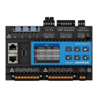
| Communication Interfaces | RS-485, Ethernet |
| Protocols | Modbus RTU, Modbus TCP |
| Storage Temperature | -20°C to +70°C |
| Weight | Approx. 350g |
| Accuracy class | Class 1 |
| Measurement Category | CAT III |