6 / 10
1 2 3
5
4
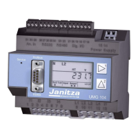
The device is a universal measurement
device for low voltage distribution systems,
which
• measures and calculates electrical variables
such as voltage, current, power, energy,
harmonics, etc. in building installations, on
distribution units, circuit breakers and busbar
trunking systems.
• transmits measurement results via interface.
The device will be installed in switch cabinets or
in small installation distributors per DIN 43880
on a 35mm mounting rail per DIN EN 60715.
• The device fulfils the application conditions
of DIN IEC 60721-3-3 and is intended for
permanent installation in locations that are
protected from the weather.
• It can be installed in any mounting position.
• Forced ventilation is not required.
6 7
Deutsche Version:
siehe Vorderseite
User manual:
Janitza electronics GmbH
Vor dem Polstück 6
35633 Lahnau, Germany
Support tel. +49 6441 9642-22
info@janitza.com | www.janitza.com
Brief description of device Assembly
Fig. Device on
mounting rail per
DIN EN 60715.
Connecting the supply voltage
cc
WARNING!
Danger of injury due to
electrical voltage!
Serious bodily injury or death can result from:
• Contact with bare or stripped live wires.
• Device inputs that are dangerous to touch.
Render the system free of voltage before
starting work! Check the system is free of
electrical energy!
The device derives its supply voltage from the
measurement voltage L1-N, L2-N and L3-N.
In doing so, at least one phase lies within the
nominal voltage range.
The device requires a voltage of at least 100V
eff
in at least one phase (L-N) for operation.
Current measurement
The device
• is only approved for measuring current with
acurrent transformer.
• is intended for the connection of current
transformers with secondary currents of
../1A and ../5A.
• has the current transformer ratio set to 5/5A
as standard.
• The current transformers must have a base
insulation according to IEC 61010-1: 2010
for the nominal voltage of the circuit.
cc
WARNING!
Danger of injury due to
electrical voltage!
Serious bodily injury or death
can result from:
• Contact with bare or stripped live wires.
• Current measurement inputs on the device
and on the current transformer that are
dangerous to touch.
Render the system free of voltage before
starting work! Check the system is free of
electrical energy!
Earth the system! Use the earth connection
points with earthing symbols for this!
Earth the secondary windings of current
transformers and all of the metal parts of
the transformer that could be touched!
Connection "Current measurement via current
transformers".
Three-phase, four-conductor
system
Single-phase, three-conductor
system
Three-phase, four-coductor
system
Voltage measurement in the
three-phase, four-conductor system
Voltage measurement in the
single-phase, three-conductor system
Voltage measurement via voltage
transformer
Connection variants for voltage measurement
CC
NOTE!
Because the device derives the supply
voltage from the measured voltage and
burdens the voltage transformer with
anon-linear current, the device is only
partially suitable for use in medium and
high voltage networks.
CC
NOTE!
Voltage transformer ratios can be
configured via the software.
Technical data
0
1
2
4
6
7
5
3
8
9
0
1
2
4
6
7
5
3
8
9
x10
(10-90)
x1
(1-9)
The green LED illuminates. Measurement
and supply voltages lie within the operating
voltage range. The device is operational.
The LED flashes for 0.5 sec. every 5 secs.
The green LED flashes.
Data transfer (RS485) is active.
The LEDs flash at the same time.
The data transfer (RS485) is faulty.
The red LED illuminates. Fault in the device!
Have the device checked by the manufacturer!
The red LED flashes. At least one current
measurement input or voltage measurement
input exceeds the measurement range.
The LEDs flash alternately.
Firmware checksum fault! Operation is
interrupted! Carry out a firmware update!
Connections and control elements
Current measurement connection
Coding switches
You can configure the device address with the
coding switches as follows:
Configure the device addresses in
the range of 01 to 99 with the coding
switches.
The device address 00 is reserved for
service purposes (further information
in the user manual).
LEDs
L1 L2 L3 N
Voltage measurement
The device derives its supply voltage from the
measured voltage.
mm
CAUTION!
Danger of injury or damage
to the device
Disregard of the connection conditions for
the voltage measurement inputs can result in
injuries or to the device being damaged.
For this reason, note that:
• The voltage measurement inputs
- are not connected to DC voltage.
- are equipped with a suitable, labelled
fuse located in the vicinity and
isolation device (alternative: circuit
breaker) located nearby.
- are dangerous to touch.
• Voltages that exceed the allowed rated
network voltages must be connected via
avoltage transformer.
• Measured voltages and measured currents
must derive from the same network.
Disconnectors
Fuse (UL/IEC listed)
Load
• The device measures voltages L-N up to 277V
and L-L up to 480V.
• The measurement and surge voltages meet
overvoltage category 300V CATIII.
CC
NOTE!
• A circuit breaker can be used as an al-
ternative to a fuse and isolating device.
• If the range is exceeded, the red LED
flashes (see step „connections and
controls“).
Typical connection variants
The following schematic shows a typical connection variant for the device with:
• Supply voltage and voltage measurement.
• Current measurement.
• RS485 interface with Modbus RTU protocol.
Connection
variant in the
"Three-phase,
four-conductor system".
CC
NOTE!
Further technical data can be found in
the user manual for the device.
1.
RS485
PC/
GridVis®
RS485
RS485
RS232 RS232
Fig. UMG 103-CBM
CC
NOTE!
Install the “GridVis®” software on the PC
to be used!
2.
USB
RS485
RS485
RS485
USB
PC/
GridVis®
3.
Connection of the device
via an UMG 604 as gateway.
UMG 604
RS485Ethernet
RS485
PC/
GridVis®
Establish connection to PC
The 3 most common connections for communication
between PC and device are described in the following:
Device connection via interface
converter.
Device connection via interface
converter.
UMG 103-CBM
UMG 103-CBM
UMG 103-CBM
UMG 103-CBM
UMG 103-CBM
UMG 103-CBM
8
1211 13
15
The PC connection of the device via the RS485
serial interface with, for example, an UMG604
as gateway (see step “Established connection to
PC”) is a method
• for configuring the device(s)
• and reading out data.
e.g. connection to the
UMG 604 as gateway
(Master)
Example: PC connection via RS485 interface and UMG 604 as gateway
e.g. connection
to further
Slave devices
RS485 bus structure
• In an RS485 bus structure (line), you connect
all devices in accordance with the Master-Slave
principle.
• One segment of an RS485 bus structure can
include up to 32 subscribers/devices.
• Terminate the cable at the start and end of a
segment with termination resistors (120Ω, 0.25W).
The device has no termination resistor.
• With more than 32 subscribers, repeaters must
be used to connect segments.
Correct
Incorrect
Terminal strip (switch cabinet).
Device with RS485 interface
(without termination resistor).
Device with RS485 interface
(termination resistor on the
device).
CC
NOTE!
The coding switches can be used in the
RS485 bus structure to allocate the Slave
devices (UMG 103-CBM)
• different device addresses.
• different device addresses to the Master
device (UMG 604).
The UMG 103-CBM detects the transmission
speed (Baud rate) automatically!
Three-phase, four-conductor
system
Single-phase, three-conductor
system
Current measurement via current
transformer in three-phase,
four-conductor system
Current measurement in the
single-phase, three-conductor
system
S1 S2
S1 S2
S1 S2
S1 S2
S1 S2
Three-phase,
four-conductor system
Current measurement via
2current transformers in three-
phase, four-conductor system
Connection variants for current measurement
CC
NOTE!
If the range is exceeded, the red LED
flashes. (see Step „connections and
control elements“)
Dok Nr. 2.057.002.1.h 07/2022 Art. Nr. 33.03.345
Mains systems
Suitable mains systems and max. rated voltages (DIN EN 61010-1/A1):
The device can be used in
• TN and TT networks
• in residential and industrial applications.
Three-phase, four-conductor systems
with earthed neutral conductor
Three-phase, four-conductor systems
with non-earthed neutral conductor
E
L1
L2
L3
E
N
R
L1
L2
L3
EE
L1
L2
EE
L
N
EE
L1
L2
L3
EE
L1
L2
N
EE
L1
L2
L3
EE
L1
L2
EE
L
N
EE
L1
L2
L3
EE
L1
L2
N
EE
U
L-N
/ U
L-L
277 VLN/480VLL
Connect in this grid system,
the device only using a voltage
transformer!
Disclaimer
The observance of the information products for
the devices is a prerequisite for safe operation
and to achieve the stipulated performance
characteristics and product characteristics.
Janitza electronics GmbH accepts no liability
for injuries to personnel, property damage
or financial losses arising due to a failure to
comply with the information products. Ensure
that your information products are accessible
and legible.
Further information can be found on our web-
site www.janitza.com at Support > Downloads.
Copyright notice
© 2016 - Janitza electronics GmbH - Lahnau.
All rights reserved. Duplication, editing,
distribution and any form of exploitation, also
as excerpts, is prohibited.
Subject to technical amendments
• Make sure that your device agrees with the
installation manual.
• Read and understand first product-related
documents.
• Keep product supporting documentation
throughout the life available and, where ap-
propriate, to pass on to subsequent users.
• Please inform yourself about device revisi-
ons and the associated adjustments to the
product-related documentation on
www.janitza.com.
Disposal
Please observe national regulations!
If disposing of individual parts, please dispose
of them in accordance with their nature and
existing country-specific regulations, for
example as:
• Electrical scrap
• Plastics
• Metals
Or, task a certified disposal business with the
scrapping.
Relevant laws, applied standards and
directives
The laws, standards and directives for the
device applied by Janitza electronic GmbH
can be found in the declaration of conformity
on our website.
General Safety
Safety information
The installation manual does not represent a full
listing of all necessary safety measures required
for safe operation of the device.
Certain operating conditions may require further
measures. The installation manual contains
information that you must observe for your
own personal safety and to avoid damage to
property.
Symbols used:
cc
This symbol is used as an addition
to the safety instructions and
warns of an electrical hazard.
mm
This symbol is used as an addition
to the safety instructions and
warns of a potential hazard.
CC
This symbol with the word NOTE!
describes:
• Procedures that do not entail
any danger of injury.
• Important information,
procedures or handling steps.
Safety instructions are highlighted with
awarning triangle and shown as follows,
depending on the degree of hazard:
mm
DANGER!
Indicates an immediately
threatening hazard that leads to
serious or even fatal injuries.
mm
WARNING!
Indicates a potentially hazardous
situation that could lead to
serious or even fatal injuries.
mm
CAUTION!
Indicates a potentially hazardous
situation that could lead to minor
injuries or damage to property.
Measures for safety
When operating electrical devices certain parts
of these devices inevitable carry dangerous
voltages. This could result in serious bodily
injury or damage to property if not handled
properly:
• Before establishing electrical connections
to the device, earth it at the ground wire
connection if there is one.
• Hazardous voltages may arise in all circuit
parts that are connected to the power supply.
• Even after disconnecting the supply voltage,
there may still be hazardous voltages
present in the device (capacitor storage).
• Do not operate equipment with current
transformer circuits when open.
• Do not exceed the limit values stipulated in
the user manual and on the rating plate - even
during testing or commissioning.
• Observe the safety and warning information in
the documents that belong to the devices!
Qualified personnel
In order to avoid injuries to personnel and
property damage, only qualified personnel with
electrical training are permitted to work on the
devices with knowledge
• of the national regulations for accident
prevention
• of safety standards
• of installation, commissioning and operation
of the device.
Proper use
The device is
• intended for installation in switch cabinets
and small installation distributors (please
observe step 3 “Assembly”).
• not intended for installation in vehicles!
The use of the device in mobile equipment
is considered to be non-standard
environmental conditions and is therefore
only permitted after separate agreement.
• not intended for installation in environments
with hazardous oils, acids, gases, vapours,
dusts, radiation, etc.
The prerequisites of faultless, safe operation
of this device are proper transport and proper
storage, set-up, installation, operation and
maintenance.
CC
NOTE!
For further information on device functions, data and assembly, see the user manual.
109
14
mm
CAUTION!
Damage to property due to
disregard of the connection
conditions or impermissible
overvoltage!
Your device can be damaged or destroyed
by a failure to comply with the connection
conditions or by exceeding the permissible
voltage range.
Before connecting the device to the supply
voltage, please check:
• Voltage and frequency correspond to the
details on the ratings plate! Limit values
stipulated in the user manual have been
complied with!
• In building installations, the supply
voltage must be protected with a UL/IEC
approved circuit breaker / a fuse!
• The isolation device
- must be installed near the device
and in a location that is easily
accessible for the user.
- must be labelled to identify the
respective device.
• Provide a fuse for the neutral conductor
if the neutral conductor terminal of the
source is not grounded.
L3
N
L1
L2
Connection variant "Direct voltage measurement
in the three-phase, four-conductor system".
Voltage measurement
3-phase, 4-conductor
systems with rated voltages
(L-N/L-L)
max. 277V/480V
Networks
Measurement in TT and TN
networks
Rated surge voltage 4kV
Protection of
voltage measurement
1 - 10A Trip characteristic B,
(With IEC / UL approval)
Overvoltage category 300V CAT III
Resolution 0.01V
Crest factor 2 (related to 240Vrms)
Sampling rate 5.4kHz
Frequency range of
the fundamental oscillation -
resolution
45Hz .. 65Hz
0.01Hz
Fourier analysis 1.-40. Harmonic
Current measurement
Nominal current 5A
Rated current 6A
Crest factor 2 (related to 6Arms)
Resolution 0.1mA
Measuring range 0.005 ... 6Arms
Overvoltage category 300V CAT II
Rated surge voltage 2kV
Power consumption approx 0.2VA (Ri=5 mΩ)
Overload for 1 sec. 60A (sinusoidal)
Sampling rate 5.4kHz
Supply voltage
The device gets the supply voltage from the measuring voltage!
Supply from single phase 115 - 277V (+-10 %), 50/60Hz
Supply from three phases 80 - 277V (+-10 %), 50/60Hz
Power consumption max. 1.5VA
General information
Net weight 200g (0.44 lb)
Device dimensions
h=98mm (3.86 in),
w=71.5mm (2.82 in),
d =46mm (1.18 in)
Transport and storage
The following information applies to devices which are trans-
ported or stored in the original packaging.
Free fall
1m (39.37 in)
Temperature
-20°C to +70°C
(-4°F to 158°F)
Ambient coditions during operation
The device
• weatherproof and use stationary!
• fulfills the conditions in accordance with DIN IEC 60721-3-3
• has protection class II according to IEC 60536 (VDE 0106,
part 1) and does not require a protective earth connection.
Operating temperature range -25°C .. +60°C (-13°F..to 140°F)
Relative humidity
5 to 95 % (at +25°C / 77°F))
without condensation
Operating altitude
0 .. 2000m (1.24 mi) above
sea level
Degree of pollution 2
Housing flammability class UL94V-0
Installed position any
Fixing/mounting
35 mm top hat rail (according to
IEC/EN 60999-1, DIN EN 50022)
Stress by impact
2 joules, IK07 according to
IEC / EN61010-1: 2010
Ventilation no external ventilation required.
Protection against ingress
of solid foreign bodies and
water
IP20 according to EN60529
September 2000, IEC60529:1989
Terminal connection capacity
Conductors to be connected.
Only one conductor can be connected per terminal!
Single core, multi-core,
fine-stranded
0.08 - 2.5mm
2
, AWG 28 - 12
Tightening torque max. 0.5Nm (0.74 ft lb)
Stripping length min. 8mm (0.32 in)
RS485 interface
Protocol, modbus RTU Modbus RTU/Slave
Transfer rate
9.6kbps, 19.2kbps,
38.4kbps, 57.6 kbps,
115.2kbps,
automatic detection
Procedure in the event of faults
Possible fault Cause Remedy
No LED lights
External fusing for the power supply voltage has tripped. Replace fuse.
Device is defective. Send device to the manufacturer for repair.
Measured current is too large
or too small. *
Current measurement in the wrong phase. Check connection and correct if necessary.
Current transformer factor programmed incorrectly. Read out current transformer ratio and program.
The peak current value at the measurement input has
been exceeded by harmonic components.
Install current transformers with a larger current
transformer ratio.
Underrange.
Install current transformers with a smaller current
transformer ratio.
Measured voltage is too large
or too small. *
Voltage measurement in the wrong phase. Check connection and correct if necessary.
Voltage transformer incorrectly programmed. Read out voltage transformer ratio and program.
Measured voltage is too
small. *
Underrange. Install voltage transformers.
The peak voltage value at the measurement input has
been exceeded by harmonic components.
Attention. It must be ensured that the measuring
inputs are not overloaded.
Active power is too large or
too small. *
The programmed current transformer transformation
ratio is incorrect.
Read out current transformer ratio and program with
the software GridVis.
The current path is assigned to the wrong voltage path. Check connection and correct if necessary.
The programmed voltage transformer transformation
ratio is incorrect.
Read out voltage transformer ratio and program.
Active power imported
supply / supply is reversed.
At least one current transformer connection is mixed
up/reversed.
Check connection and correct, if necessary.
A current path is assigned to the wrong voltage path.
No connection with the device. RS485: Device address is incorrect or wrong protocol. Adjust the device address / select protocol.
Despite the measures above
the device does not work.
Device is defective.
Send device and error description to verify the
manufacturer.
*...
m m CAUTION!
Material damage from overloaded measurement inputs!
Too high current and voltage values overload the measurement inputs.
Observe the limits stated on the nameplate and in the user manual!
UMG 103-CBM
RS485
2 3
AB
1
Data GND
Strommessung
Current measurement
Mess- und Versorgungsspannung
Measuring and supply voltage
Verbraucher
Load
A
B
C
S2
S2
S2
S1
S1
S1
Measurement data recording
Memory (Flash) 4MB
Battery (soldered)
Typical life expectancy
BR 1632, 3V
8-10years
B
A
C
RS485 bus
A
B
A
B
Data GND
Fig. UMG 103-CBM
B
A
C
Red LED
Green LED
Coding
switches
for setting the
device address
RS485
Interface
Connection of measurement
voltage and supply voltage
B
A
C
Power Analyser
UMG 103-CBM
Installation manual
(firmware 2.0 and higher)
• Installation
• Device settings
L2
L3
L1
S
2
S
1
S
2
S
1
S
2
S
1
B
A
C
cc
WARNING!
Danger of injury due
to high currents and high
electrical voltages!
Current transformers operating with an open
secondary circuit (high voltage peaks) can
result in serious or even fatal injuries.
Avoid open operation of the current transformers
- short-circuit unloaded transformers!
CC
NOTE!
• Further information on current trans-
formers can be found in the user
manual.
• Current transformer ratios can be
configured via the software.
Consumer
www.janitza.com
1
2 3
5
4
The device is a universal measurement
device for low voltage distribution systems,
which
• measures and calculates electrical variables
such as voltage, current, power, energy,
harmonics, etc. in building installations, on
distribution units, circuit breakers and busbar
trunking systems.
• transmits measurement results via interface.
The device will be installed in switch cabinets or
in small installation distributors per DIN 43880
on a 35mm mounting rail per DIN EN 60715.
• The device fulfils the application conditions
of DIN IEC 60721-3-3 and is intended for
permanent installation in locations that are
protected from the weather.
• It can be installed in any mounting position.
• Forced ventilation is not required.
6 7
Deutsche Version:
siehe Vorderseite
User manual:
Janitza electronics GmbH
Vor dem Polstück 6
35633 Lahnau, Germany
Support tel. +49 6441 9642-22
info@janitza.com | www.janitza.com
Brief description of device Assembly
Fig. Device on
mounting rail per
DIN EN 60715.
Connecting the supply voltage
cc
WARNING!
Danger of injury due to
electrical voltage!
Serious bodily injury or death can result from:
• Contact with bare or stripped live wires.
• Device inputs that are dangerous to touch.
Render the system free of voltage before
starting work! Check the system is free of
electrical energy!
The device derives its supply voltage from the
measurement voltage L1-N, L2-N and L3-N.
In doing so, at least one phase lies within the
nominal voltage range.
The device requires a voltage of at least 100V
eff
in at least one phase (L-N) for operation.
Current measurement
The device
• is only approved for measuring current with
acurrent transformer.
• is intended for the connection of current
transformers with secondary currents of
../1A and ../5A.
• has the current transformer ratio set to 5/5A
as standard.
• The current transformers must have a base
insulation according to IEC 61010-1: 2010
for the nominal voltage of the circuit.
cc
WARNING!
Danger of injury due to
electrical voltage!
Serious bodily injury or death
can result from:
• Contact with bare or stripped live wires.
• Current measurement inputs on the device
and on the current transformer that are
dangerous to touch.
Render the system free of voltage before
starting work! Check the system is free of
electrical energy!
Earth the system! Use the earth connection
points with earthing symbols for this!
Earth the secondary windings of current
transformers and all of the metal parts of
the transformer that could be touched!
Connection "Current measurement via current
transformers".
Three-phase, four-conductor
system
Single-phase, three-conductor
system
Three-phase, four-coductor
system
Voltage measurement in the
three-phase, four-conductor system
Voltage measurement in the
single-phase, three-conductor system
Voltage measurement via voltage
transformer
Connection variants for voltage measurement
CC
NOTE!
Because the device derives the supply
voltage from the measured voltage and
burdens the voltage transformer with
anon-linear current, the device is only
partially suitable for use in medium and
high voltage networks.
CC
NOTE!
Voltage transformer ratios can be
configured via the software.
Technical data
0
1
2
4
6
7
5
3
8
9
0
1
2
4
6
7
5
3
8
9
x10
(10-90)
x1
(1-9)
The green LED illuminates. Measurement
and supply voltages lie within the operating
voltage range. The device is operational.
The LED flashes for 0.5 sec. every 5 secs.
The green LED flashes.
Data transfer (RS485) is active.
The LEDs flash at the same time.
The data transfer (RS485) is faulty.
The red LED illuminates. Fault in the device!
Have the device checked by the manufacturer!
The red LED flashes. At least one current
measurement input or voltage measurement
input exceeds the measurement range.
The LEDs flash alternately.
Firmware checksum fault! Operation is
interrupted! Carry out a firmware update!
Connections and control elements
Current measurement connection
Coding switches
You can configure the device address with the
coding switches as follows:
Configure the device addresses in
the range of 01 to 99 with the coding
switches.
The device address 00 is reserved for
service purposes (further information
in the user manual).
LEDs
L1 L2 L3 N
Voltage measurement
The device derives its supply voltage from the
measured voltage.
mm
CAUTION!
Danger of injury or damage
to the device
Disregard of the connection conditions for
the voltage measurement inputs can result in
injuries or to the device being damaged.
For this reason, note that:
• The voltage measurement inputs
- are not connected to DC voltage.
- are equipped with a suitable, labelled
fuse located in the vicinity and
isolation device (alternative: circuit
breaker) located nearby.
- are dangerous to touch.
• Voltages that exceed the allowed rated
network voltages must be connected via
avoltage transformer.
• Measured voltages and measured currents
must derive from the same network.
Disconnectors
Fuse (UL/IEC listed)
Load
• The device measures voltages L-N up to 277V
and L-L up to 480V.
• The measurement and surge voltages meet
overvoltage category 300V CATIII.
CC
NOTE!
• A circuit breaker can be used as an al-
ternative to a fuse and isolating device.
• If the range is exceeded, the red LED
flashes (see step „connections and
controls“).
Typical connection variants
The following schematic shows a typical connection variant for the device with:
• Supply voltage and voltage measurement.
• Current measurement.
• RS485 interface with Modbus RTU protocol.
Connection
variant in the
"Three-phase,
four-conductor system".
CC
NOTE!
Further technical data can be found in
the user manual for the device.
1.
RS485
PC/
GridVis®
RS485
RS485
RS232 RS232
Fig. UMG 103-CBM
CC
NOTE!
Install the “GridVis®” software on the PC
to be used!
2.
USB
RS485
RS485
RS485
USB
PC/
GridVis®
3.
Connection of the device
via an UMG 604 as gateway.
UMG 604
RS485Ethernet
RS485
PC/
GridVis®
Establish connection to PC
The 3 most common connections for communication
between PC and device are described in the following:
Device connection via interface
converter.
Device connection via interface
converter.
UMG 103-CBM
UMG 103-CBM
UMG 103-CBM
UMG 103-CBM
UMG 103-CBM
UMG 103-CBM
8
1211 13
15
The PC connection of the device via the RS485
serial interface with, for example, an UMG604
as gateway (see step “Established connection to
PC”) is a method
• for configuring the device(s)
• and reading out data.
e.g. connection to the
UMG 604 as gateway
(Master)
Example: PC connection via RS485 interface and UMG 604 as gateway
e.g. connection
to further
Slave devices
RS485 bus structure
• In an RS485 bus structure (line), you connect
all devices in accordance with the Master-Slave
principle.
• One segment of an RS485 bus structure can
include up to 32 subscribers/devices.
• Terminate the cable at the start and end of a
segment with termination resistors (120Ω, 0.25W).
The device has no termination resistor.
• With more than 32 subscribers, repeaters must
be used to connect segments.
Correct
Incorrect
Terminal strip (switch cabinet).
Device with RS485 interface
(without termination resistor).
Device with RS485 interface
(termination resistor on the
device).
CC
NOTE!
The coding switches can be used in the
RS485 bus structure to allocate the Slave
devices (UMG 103-CBM)
• different device addresses.
• different device addresses to the Master
device (UMG 604).
The UMG 103-CBM detects the transmission
speed (Baud rate) automatically!
Three-phase, four-conductor
system
Single-phase, three-conductor
system
Current measurement via current
transformer in three-phase,
four-conductor system
Current measurement in the
single-phase, three-conductor
system
S1 S2
S1 S2
S1 S2
S1 S2
S1 S2
Three-phase,
four-conductor system
Current measurement via
2current transformers in three-
phase, four-conductor system
Connection variants for current measurement
CC
NOTE!
If the range is exceeded, the red LED
flashes. (see Step „connections and
control elements“)
Dok Nr. 2.057.002.1.h 07/2022 Art. Nr. 33.03.345
Mains systems
Suitable mains systems and max. rated voltages (DIN EN 61010-1/A1):
The device can be used in
• TN and TT networks
• in residential and industrial applications.
Three-phase, four-conductor systems
with earthed neutral conductor
Three-phase, four-conductor systems
with non-earthed neutral conductor
E
L1
L2
L3
E
N
R
L1
L2
L3
EE
L1
L2
EE
L
N
EE
L1
L2
L3
EE
L1
L2
N
EE
L1
L2
L3
EE
L1
L2
EE
L
N
EE
L1
L2
L3
EE
L1
L2
N
EE
U
L-N
/ U
L-L
277 VLN/480VLL
Connect in this grid system,
the device only using a voltage
transformer!
Disclaimer
The observance of the information products for
the devices is a prerequisite for safe operation
and to achieve the stipulated performance
characteristics and product characteristics.
Janitza electronics GmbH accepts no liability
for injuries to personnel, property damage
or financial losses arising due to a failure to
comply with the information products. Ensure
that your information products are accessible
and legible.
Further information can be found on our web-
site www.janitza.com at Support > Downloads.
Copyright notice
© 2016 - Janitza electronics GmbH - Lahnau.
All rights reserved. Duplication, editing,
distribution and any form of exploitation, also
as excerpts, is prohibited.
Subject to technical amendments
• Make sure that your device agrees with the
installation manual.
• Read and understand first product-related
documents.
• Keep product supporting documentation
throughout the life available and, where ap-
propriate, to pass on to subsequent users.
• Please inform yourself about device revisi-
ons and the associated adjustments to the
product-related documentation on
www.janitza.com.
Disposal
Please observe national regulations!
If disposing of individual parts, please dispose
of them in accordance with their nature and
existing country-specific regulations, for
example as:
• Electrical scrap
• Plastics
• Metals
Or, task a certified disposal business with the
scrapping.
Relevant laws, applied standards and
directives
The laws, standards and directives for the
device applied by Janitza electronic GmbH
can be found in the declaration of conformity
on our website.
General
Safety
Safety information
The installation manual does not represent a full
listing of all necessary safety measures required
for safe operation of the device.
Certain operating conditions may require further
measures. The installation manual contains
information that you must observe for your
own personal safety and to avoid damage to
property.
Symbols used:
cc
This symbol is used as an addition
to the safety instructions and
warns of an electrical hazard.
mm
This symbol is used as an addition
to the safety instructions and
warns of a potential hazard.
CC
This symbol with the word NOTE!
describes:
• Procedures that do not entail
any danger of injury.
• Important information,
procedures or handling steps.
Safety instructions are highlighted with
awarning triangle and shown as follows,
depending on the degree of hazard:
mm
DANGER!
Indicates an immediately
threatening hazard that leads to
serious or even fatal injuries.
mm
WARNING!
Indicates a potentially hazardous
situation that could lead to
serious or even fatal injuries.
mm
CAUTION!
Indicates a potentially hazardous
situation that could lead to minor
injuries or damage to property.
Measures for safety
When operating electrical devices certain parts
of these devices inevitable carry dangerous
voltages. This could result in serious bodily
injury or damage to property if not handled
properly:
• Before establishing electrical connections
to the device, earth it at the ground wire
connection if there is one.
• Hazardous voltages may arise in all circuit
parts that are connected to the power supply.
• Even after disconnecting the supply voltage,
there may still be hazardous voltages
present in the device (capacitor storage).
• Do not operate equipment with current
transformer circuits when open.
• Do not exceed the limit values stipulated in
the user manual and on the rating plate - even
during testing or commissioning.
• Observe the safety and warning information in
the documents that belong to the devices!
Qualified personnel
In order to avoid injuries to personnel and
property damage, only qualified personnel with
electrical training are permitted to work on the
devices with knowledge
• of the national regulations for accident
prevention
• of safety standards
• of installation, commissioning and operation
of the device.
Proper use
The device is
• intended for installation in switch cabinets
and small installation distributors (please
observe step 3 “Assembly”).
• not intended for installation in vehicles!
The use of the device in mobile equipment
is considered to be non-standard
environmental conditions and is therefore
only permitted after separate agreement.
• not intended for installation in environments
with hazardous oils, acids, gases, vapours,
dusts, radiation, etc.
The prerequisites of faultless, safe operation
of this device are proper transport and proper
storage, set-up, installation, operation and
maintenance.
CC
NOTE!
For further information on device functions, data and assembly, see the user manual.
109
14
mm
CAUTION!
Damage to property due to
disregard of the connection
conditions or impermissible
overvoltage!
Your device can be damaged or destroyed
by a failure to comply with the connection
conditions or by exceeding the permissible
voltage range.
Before connecting the device to the supply
voltage, please check:
• Voltage and frequency correspond to the
details on the ratings plate! Limit values
stipulated in the user manual have been
complied with!
• In building installations, the supply
voltage must be protected with a UL/IEC
approved circuit breaker / a fuse!
• The isolation device
- must be installed near the device
and in a location that is easily
accessible for the user.
- must be labelled to identify the
respective device.
• Provide a fuse for the neutral conductor
if the neutral conductor terminal of the
source is not grounded.
L3
N
L1
L2
Connection variant "Direct voltage measurement
in the three-phase, four-conductor system".
Voltage measurement
3-phase, 4-conductor
systems with rated voltages
(L-N/L-L)
max. 277V/480V
Networks
Measurement in TT and TN
networks
Rated surge voltage 4kV
Protection of
voltage measurement
1 - 10A Trip characteristic B,
(With IEC / UL approval)
Overvoltage category 300V CAT III
Resolution 0.01V
Crest factor 2 (related to 240Vrms)
Sampling rate 5.4kHz
Frequency range of
the fundamental oscillation -
resolution
45Hz .. 65Hz
0.01Hz
Fourier analysis 1.-40. Harmonic
Current measurement
Nominal current 5A
Rated current 6A
Crest factor 2 (related to 6Arms)
Resolution 0.1mA
Measuring range 0.005 ... 6Arms
Overvoltage category 300V CAT II
Rated surge voltage 2kV
Power consumption approx 0.2VA (Ri=5 mΩ)
Overload for 1 sec. 60A (sinusoidal)
Sampling rate 5.4kHz
Supply voltage
The device gets the supply voltage from the measuring voltage!
Supply from single phase 115 - 277V (+-10 %), 50/60Hz
Supply from three phases 80 - 277V (+-10 %), 50/60Hz
Power consumption max. 1.5VA
General information
Net weight 200g (0.44 lb)
Device dimensions
h=98mm (3.86 in),
w=71.5mm (2.82 in),
d =46mm (1.18 in)
Transport and storage
The following information applies to devices which are trans-
ported or stored in the original packaging.
Free fall
1m (39.37 in)
Temperature
-20°C to +70°C
(-4°F to 158°F)
Ambient coditions during operation
The device
• weatherproof and use stationary!
• fulfills the conditions in accordance with DIN IEC 60721-3-3
• has protection class II according to IEC 60536 (VDE 0106,
part 1) and does not require a protective earth connection.
Operating temperature range -25°C .. +60°C (-13°F..to 140°F)
Relative humidity
5 to 95 % (at +25°C / 77°F))
without condensation
Operating altitude
0 .. 2000m (1.24 mi) above
sea level
Degree of pollution 2
Housing flammability class UL94V-0
Installed position any
Fixing/mounting
35 mm top hat rail (according to
IEC/EN 60999-1, DIN EN 50022)
Stress by impact
2 joules, IK07 according to
IEC / EN61010-1: 2010
Ventilation no external ventilation required.
Protection against ingress
of solid foreign bodies and
water
IP20 according to EN60529
September 2000, IEC60529:1989
Terminal connection capacity
Conductors to be connected.
Only one conductor can be connected per terminal!
Single core, multi-core,
fine-stranded
0.08 - 2.5mm
2
, AWG 28 - 12
Tightening torque max. 0.5Nm (0.74 ft lb)
Stripping length min. 8mm (0.32 in)
RS485 interface
Protocol, modbus RTU Modbus RTU/Slave
Transfer rate
9.6kbps, 19.2kbps,
38.4kbps, 57.6 kbps,
115.2kbps,
automatic detection
Procedure in the event of faults
Possible fault Cause Remedy
No LED lights
External fusing for the power supply voltage has tripped. Replace fuse.
Device is defective. Send device to the manufacturer for repair.
Measured current is too large
or too small. *
Current measurement in the wrong phase. Check connection and correct if necessary.
Current transformer factor programmed incorrectly. Read out current transformer ratio and program.
The peak current value at the measurement input has
been exceeded by harmonic components.
Install current transformers with a larger current
transformer ratio.
Underrange.
Install current transformers with a smaller current
transformer ratio.
Measured voltage is too large
or too small. *
Voltage measurement in the wrong phase. Check connection and correct if necessary.
Voltage transformer incorrectly programmed. Read out voltage transformer ratio and program.
Measured voltage is too
small. *
Underrange. Install voltage transformers.
The peak voltage value at the measurement input has
been exceeded by harmonic components.
Attention. It must be ensured that the measuring
inputs are not overloaded.
Active power is too large or
too small. *
The programmed current transformer transformation
ratio is incorrect.
Read out current transformer ratio and program with
the software GridVis.
The current path is assigned to the wrong voltage path. Check connection and correct if necessary.
The programmed voltage transformer transformation
ratio is incorrect.
Read out voltage transformer ratio and program.
Active power imported
supply / supply is reversed.
At least one current transformer connection is mixed
up/reversed.
Check connection and correct, if necessary.
A current path is assigned to the wrong voltage path.
No connection with the device. RS485: Device address is incorrect or wrong protocol. Adjust the device address / select protocol.
Despite the measures above
the device does not work.
Device is defective.
Send device and error description to verify the
manufacturer.
*...
m m CAUTION!
Material damage from overloaded measurement inputs!
Too high current and voltage values overload the measurement inputs.
Observe the limits stated on the nameplate and in the user manual!
UMG 103-CBM
RS485
2 3
AB
1
Data GND
Strommessung
Current measurement
Mess- und Versorgungsspannung
Measuring and supply voltage
Verbraucher
Load
A
B
C
S2
S2
S2
S1
S1
S1
Measurement data recording
Memory (Flash) 4MB
Battery (soldered)
Typical life expectancy
BR 1632, 3V
8-10years
B
A
C
RS485 bus
A
B
A
B
Data GND
Fig. UMG 103-CBM
B
A
C
Red LED
Green LED
Coding
switches
for setting the
device address
RS485
Interface
Connection of measurement
voltage and supply voltage
B
A
C
Power Analyser
UMG 103-CBM
Installation manual
(firmware 2.0 and higher)
• Installation
• Device settings
L2
L3
L1
S
2
S
1
S
2
S
1
S
2
S
1
B
A
C
cc
WARNING!
Danger of injury due
to high currents and high
electrical voltages!
Current transformers operating with an open
secondary circuit (high voltage peaks) can
result in serious or even fatal injuries.
Avoid open operation of the current transformers
- short-circuit unloaded transformers!
CC
NOTE!
• Further information on current trans-
formers can be found in the user
manual.
• Current transformer ratios can be
configured via the software.
Consumer
www.janitza.com
L
L
L
N
1 2 3
2
3
5
4
The device is a universal measurement
device for low voltage distribution systems,
which
• measures and calculates electrical variables
such as voltage, current, power, energy,
harmonics, etc. in building installations, on
distribution units, circuit breakers and busbar
trunking systems.
• transmits measurement results via interface.
The device will be installed in switch cabinets or
in small installation distributors per DIN 43880
on a 35mm mounting rail per DIN EN 60715.
• The device fulfils the application conditions
of DIN IEC 60721-3-3 and is intended for
permanent installation in locations that are
protected from the weather.
• It can be installed in any mounting position.
• Forced ventilation is not required.
6 7
Deutsche Version:
siehe Vorderseite
User manual:
Janitza electronics GmbH
Vor dem Polstück 6
35633 Lahnau, Germany
Support tel. +49 6441 9642-22
info@janitza.com | www.janitza.com
Brief description of device Assembly
Fig. Device on
mounting rail per
DIN EN 60715.
Connecting the supply voltage
cc
WARNING!
Danger of injury due to
electrical voltage!
Serious bodily injury or death can result from:
• Contact with bare or stripped live wires.
• Device inputs that are dangerous to touch.
Render the system free of voltage before
starting work! Check the system is free of
electrical energy!
The device derives its supply voltage from the
measurement voltage L1-N, L2-N and L3-N.
In doing so, at least one phase lies within the
nominal voltage range.
The device requires a voltage of at least 100V
eff
in at least one phase (L-N) for operation.
Current measurement
The device
• is only approved for measuring current with
acurrent transformer.
• is intended for the connection of current
transformers with secondary currents of
../1A and ../5A.
• has the current transformer ratio set to 5/5A
as standard.
• The current transformers must have a base
insulation according to IEC 61010-1: 2010
for the nominal voltage of the circuit.
cc
WARNING!
Danger of injury due to
electrical voltage!
Serious bodily injury or death
can result from:
• Contact with bare or stripped live wires.
• Current measurement inputs on the device
and on the current transformer that are
dangerous to touch.
Render the system free of voltage before
starting work! Check the system is free of
electrical energy!
Earth the system! Use the earth connection
points with earthing symbols for this!
Earth the secondary windings of current
transformers and all of the metal parts of
the transformer that could be touched!
Connection "Current measurement via current
transformers".
Three-phase, four-conductor
system
Single-phase, three-conductor
system
Three-phase, four-coductor
system
Voltage measurement in the
three-phase, four-conductor system
Voltage measurement in the
single-phase, three-conductor system
Voltage measurement via voltage
transformer
Connection variants for voltage measurement
CC
NOTE!
Because the device derives the supply
voltage from the measured voltage and
burdens the voltage transformer with
anon-linear current, the device is only
partially suitable for use in medium and
high voltage networks.
CC
NOTE!
Voltage transformer ratios can be
configured via the software.
Technical data
0
1
2
4
6
7
5
3
8
9
0
1
2
4
6
7
5
3
8
9
x10
(10-90)
x1
(1-9)
The green LED illuminates. Measurement
and supply voltages lie within the operating
voltage range. The device is operational.
The LED flashes for 0.5 sec. every 5 secs.
The green LED flashes.
Data transfer (RS485) is active.
The LEDs flash at the same time.
The data transfer (RS485) is faulty.
The red LED illuminates. Fault in the device!
Have the device checked by the manufacturer!
The red LED flashes. At least one current
measurement input or voltage measurement
input exceeds the measurement range.
The LEDs flash alternately.
Firmware checksum fault! Operation is
interrupted! Carry out a firmware update!
Connections and control elements
Current measurement connection
Coding switches
You can configure the device address with the
coding switches as follows:
Configure the device addresses in
the range of 01 to 99 with the coding
switches.
The device address 00 is reserved for
service purposes (further information
in the user manual).
LEDs
L1 L2 L3 N
Voltage measurement
The device derives its supply voltage from the
measured voltage.
mm
CAUTION!
Danger of injury or damage
to the device
Disregard of the connection conditions for
the voltage measurement inputs can result in
injuries or to the device being damaged.
For this reason, note that:
• The voltage measurement inputs
- are not connected to DC voltage.
- are equipped with a suitable, labelled
fuse located in the vicinity and
isolation device (alternative: circuit
breaker) located nearby.
- are dangerous to touch.
• Voltages that exceed the allowed rated
network voltages must be connected via
avoltage transformer.
• Measured voltages and measured currents
must derive from the same network.
Disconnectors
Fuse (UL/IEC listed)
Load
• The device measures voltages L-N up to 277V
and L-L up to 480V.
• The measurement and surge voltages meet
overvoltage category 300V CATIII.
CC
NOTE!
• A circuit breaker can be used as an al-
ternative to a fuse and isolating device.
• If the range is exceeded, the red LED
flashes (see step „connections and
controls“).
Typical connection variants
The following schematic shows a typical connection variant for the device with:
• Supply voltage and voltage measurement.
• Current measurement.
• RS485 interface with Modbus RTU protocol.
Connection
variant in the
"Three-phase,
four-conductor system".
CC
NOTE!
Further technical data can be found in
the user manual for the device.
1.
RS485
PC/
GridVis®
RS485
RS485
RS232 RS232
Fig. UMG 103-CBM
CC
NOTE!
Install the “GridVis®” software on the PC
to be used!
2.
USB
RS485
RS485
RS485
USB
PC/
GridVis®
3.
Connection of the device
via an UMG 604 as gateway.
UMG 604
RS485Ethernet
RS485
PC/
GridVis®
Establish connection to PC
The 3 most common connections for communication
between PC and device are described in the following:
Device connection via interface
converter.
Device connection via interface
converter.
UMG 103-CBM
UMG 103-CBM
UMG 103-CBM
UMG 103-CBM
UMG 103-CBM
UMG 103-CBM
8
1211 13
15
The PC connection of the device via the RS485
serial interface with, for example, an UMG604
as gateway (see step “Established connection to
PC”) is a method
• for configuring the device(s)
• and reading out data.
e.g. connection to the
UMG 604 as gateway
(Master)
Example: PC connection via RS485 interface and UMG 604 as gateway
e.g. connection
to further
Slave devices
RS485 bus structure
• In an RS485 bus structure (line), you connect
all devices in accordance with the Master-Slave
principle.
• One segment of an RS485 bus structure can
include up to 32 subscribers/devices.
• Terminate the cable at the start and end of a
segment with termination resistors (120Ω, 0.25W).
The device has no termination resistor.
• With more than 32 subscribers, repeaters must
be used to connect segments.
Correct
Incorrect
Terminal strip (switch cabinet).
Device with RS485 interface
(without termination resistor).
Device with RS485 interface
(termination resistor on the
device).
CC
NOTE!
The coding switches can be used in the
RS485 bus structure to allocate the Slave
devices (UMG 103-CBM)
• different device addresses.
• different device addresses to the Master
device (UMG 604).
The UMG 103-CBM detects the transmission
speed (Baud rate) automatically!
Three-phase, four-conductor
system
Single-phase, three-conductor
system
Current measurement via current
transformer in three-phase,
four-conductor system
Current measurement in the
single-phase, three-conductor
system
S1 S2
S1 S2
S1 S2
S1 S2
S1 S2
Three-phase,
four-conductor system
Current measurement via
2current transformers in three-
phase, four-conductor system
Connection variants for current measurement
CC
NOTE!
If the range is exceeded, the red LED
flashes. (see Step „connections and
control elements“)
Dok Nr. 2.057.002.1.h 07/2022 Art. Nr. 33.03.345
Mains systems
Suitable mains systems and max. rated voltages (DIN EN 61010-1/A1):
The device can be used in
• TN and TT networks
• in residential and industrial applications.
Three-phase, four-conductor systems
with earthed neutral conductor
Three-phase, four-conductor systems
with non-earthed neutral conductor
E
L1
L2
L3
E
N
R
L1
L2
L3
EE
L1
L2
EE
L
N
EE
L1
L2
L3
EE
L1
L2
N
EE
L1
L2
L3
EE
L1
L2
EE
L
N
EE
L1
L2
L3
EE
L1
L2
N
EE
U
L-N
/ U
L-L
277 VLN/480VLL
Connect in this grid system,
the device only using a voltage
transformer!
Disclaimer
The observance of the information products for
the devices is a prerequisite for safe operation
and to achieve the stipulated performance
characteristics and product characteristics.
Janitza electronics GmbH accepts no liability
for injuries to personnel, property damage
or financial losses arising due to a failure to
comply with the information products. Ensure
that your information products are accessible
and legible.
Further information can be found on our web-
site www.janitza.com at Support > Downloads.
Copyright notice
© 2016 - Janitza electronics GmbH - Lahnau.
All rights reserved. Duplication, editing,
distribution and any form of exploitation, also
as excerpts, is prohibited.
Subject to technical amendments
• Make sure that your device agrees with the
installation manual.
• Read and understand first product-related
documents.
• Keep product supporting documentation
throughout the life available and, where ap-
propriate, to pass on to subsequent users.
• Please inform yourself about device revisi-
ons and the associated adjustments to the
product-related documentation on
www.janitza.com.
Disposal
Please observe national regulations!
If disposing of individual parts, please dispose
of them in accordance with their nature and
existing country-specific regulations, for
example as:
• Electrical scrap
• Plastics
• Metals
Or, task a certified disposal business with the
scrapping.
Relevant laws, applied standards and
directives
The laws, standards and directives for the
device applied by Janitza electronic GmbH
can be found in the declaration of conformity
on our website.
General
Safety
Safety information
The installation manual does not represent a full
listing of all necessary safety measures required
for safe operation of the device.
Certain operating conditions may require further
measures. The installation manual contains
information that you must observe for your
own personal safety and to avoid damage to
property.
Symbols used:
c
This symbol is used as an addition
to the safety instructions and
warns of an electrical hazard.
m
This symbol is used as an addition
to the safety instructions and
warns of a potential hazard.
C
This symbol with the word NOTE!
describes:
• Procedures that do not entail
any danger of injury.
• Important information,
procedures or handling steps.
Safety instructions are highlighted with
awarning triangle and shown as follows,
depending on the degree of hazard:
m
DANGER!
Indicates an immediately
threatening hazard that leads to
serious or even fatal injuries.
m
WARNING!
Indicates a potentially hazardous
situation that could lead to
serious or even fatal injuries.
m
CAUTION!
Indicates a potentially hazardous
situation that could lead to minor
injuries or damage to property.
Measures for safety
When operating electrical devices certain parts
of these devices inevitable carry dangerous
voltages. This could result in serious bodily
injury or damage to property if not handled
properly:
• Before establishing electrical connections
to the device, earth it at the ground wire
connection if there is one.
• Hazardous voltages may arise in all circuit
parts that are connected to the power supply.
• Even after disconnecting the supply voltage,
there may still be hazardous voltages
present in the device (capacitor storage).
• Do not operate equipment with current
transformer circuits when open.
• Do not exceed the limit values stipulated in
the user manual and on the rating plate - even
during testing or commissioning.
• Observe the safety and warning information in
the documents that belong to the devices!
Qualified personnel
In order to avoid injuries to personnel and
property damage, only qualified personnel with
electrical training are permitted to work on the
devices with knowledge
• of the national regulations for accident
prevention
• of safety standards
• of installation, commissioning and operation
of the device.
Proper use
The device is
• intended for installation in switch cabinets
and small installation distributors (please
observe step 3 “Assembly”).
• not intended for installation in vehicles!
The use of the device in mobile equipment
is considered to be non-standard
environmental conditions and is therefore
only permitted after separate agreement.
• not intended for installation in environments
with hazardous oils, acids, gases, vapours,
dusts, radiation, etc.
The prerequisites of faultless, safe operation
of this device are proper transport and proper
storage, set-up, installation, operation and
maintenance.
CC
NOTE!
For further information on device functions, data and assembly, see the user manual.
109
14
mm
CAUTION!
Damage to property due to
disregard of the connection
conditions or impermissible
overvoltage!
Your device can be damaged or destroyed
by a failure to comply with the connection
conditions or by exceeding the permissible
voltage range.
Before connecting the device to the supply
voltage, please check:
• Voltage and frequency correspond to the
details on the ratings plate! Limit values
stipulated in the user manual have been
complied with!
• In building installations, the supply
voltage must be protected with a UL/IEC
approved circuit breaker / a fuse!
• The isolation device
- must be installed near the device
and in a location that is easily
accessible for the user.
- must be labelled to identify the
respective device.
• Provide a fuse for the neutral conductor
if the neutral conductor terminal of the
source is not grounded.
L3
N
L1
L2
Connection variant "Direct voltage measurement
in the three-phase, four-conductor system".
Voltage measurement
3-phase, 4-conductor
systems with rated voltages
(L-N/L-L)
max. 277V/480V
Networks
Measurement in TT and TN
networks
Rated surge voltage 4kV
Protection of
voltage measurement
1 - 10A Trip characteristic B,
(With IEC / UL approval)
Overvoltage category 300V CAT III
Resolution 0.01V
Crest factor 2 (related to 240Vrms)
Sampling rate 5.4kHz
Frequency range of
the fundamental oscillation -
resolution
45Hz .. 65Hz
0.01Hz
Fourier analysis 1.-40. Harmonic
Current measurement
Nominal current 5A
Rated current 6A
Crest factor 2 (related to 6Arms)
Resolution 0.1mA
Measuring range 0.005 ... 6Arms
Overvoltage category 300V CAT II
Rated surge voltage 2kV
Power consumption approx 0.2VA (Ri=5 mΩ)
Overload for 1 sec. 60A (sinusoidal)
Sampling rate 5.4kHz
Supply voltage
The device gets the supply voltage from the measuring voltage!
Supply from single phase 115 - 277V (+-10 %), 50/60Hz
Supply from three phases 80 - 277V (+-10 %), 50/60Hz
Power consumption max. 1.5VA
General information
Net weight 200g (0.44 lb)
Device dimensions
h=98mm (3.86 in),
w=71.5mm (2.82 in),
d =46mm (1.18 in)
Transport and storage
The following information applies to devices which are trans-
ported or stored in the original packaging.
Free fall
1m (39.37 in)
Temperature
-20°C to +70°C
(-4°F to 158°F)
Ambient coditions during operation
The device
• weatherproof and use stationary!
• fulfills the conditions in accordance with DIN IEC 60721-3-3
• has protection class II according to IEC 60536 (VDE 0106,
part 1) and does not require a protective earth connection.
Operating temperature range -25°C .. +60°C (-13°F..to 140°F)
Relative humidity
5 to 95 % (at +25°C / 77°F))
without condensation
Operating altitude
0 .. 2000m (1.24 mi) above
sea level
Degree of pollution 2
Housing flammability class UL94V-0
Installed position any
Fixing/mounting
35 mm top hat rail (according to
IEC/EN 60999-1, DIN EN 50022)
Stress by impact
2 joules, IK07 according to
IEC / EN61010-1: 2010
Ventilation no external ventilation required.
Protection against ingress
of solid foreign bodies and
water
IP20 according to EN60529
September 2000, IEC60529:1989
Terminal connection capacity
Conductors to be connected.
Only one conductor can be connected per terminal!
Single core, multi-core,
fine-stranded
0.08 - 2.5mm
2
, AWG 28 - 12
Tightening torque max. 0.5Nm (0.74 ft lb)
Stripping length min. 8mm (0.32 in)
RS485 interface
Protocol, modbus RTU Modbus RTU/Slave
Transfer rate
9.6kbps, 19.2kbps,
38.4kbps, 57.6 kbps,
115.2kbps,
automatic detection
Procedure in the event of faults
Possible fault Cause Remedy
No LED lights
External fusing for the power supply voltage has tripped. Replace fuse.
Device is defective. Send device to the manufacturer for repair.
Measured current is too large
or too small. *
Current measurement in the wrong phase. Check connection and correct if necessary.
Current transformer factor programmed incorrectly. Read out current transformer ratio and program.
The peak current value at the measurement input has
been exceeded by harmonic components.
Install current transformers with a larger current
transformer ratio.
Underrange.
Install current transformers with a smaller current
transformer ratio.
Measured voltage is too large
or too small. *
Voltage measurement in the wrong phase. Check connection and correct if necessary.
Voltage transformer incorrectly programmed. Read out voltage transformer ratio and program.
Measured voltage is too
small. *
Underrange. Install voltage transformers.
The peak voltage value at the measurement input has
been exceeded by harmonic components.
Attention. It must be ensured that the measuring
inputs are not overloaded.
Active power is too large or
too small. *
The programmed current transformer transformation
ratio is incorrect.
Read out current transformer ratio and program with
the software GridVis.
The current path is assigned to the wrong voltage path. Check connection and correct if necessary.
The programmed voltage transformer transformation
ratio is incorrect.
Read out voltage transformer ratio and program.
Active power imported
supply / supply is reversed.
At least one current transformer connection is mixed
up/reversed.
Check connection and correct, if necessary.
A current path is assigned to the wrong voltage path.
No connection with the device. RS485: Device address is incorrect or wrong protocol. Adjust the device address / select protocol.
Despite the measures above
the device does not work.
Device is defective.
Send device and error description to verify the
manufacturer.
*...
m m CAUTION!
Material damage from overloaded measurement inputs!
Too high current and voltage values overload the measurement inputs.
Observe the limits stated on the nameplate and in the user manual!
UMG 103-CBM
RS485
2 3
AB
1
Data GND
Strommessung
Current measurement
Mess- und Versorgungsspannung
Measuring and supply voltage
Verbraucher
Load
A
B
C
S2
S2
S2
S1
S1
S1
Measurement data recording
Memory (Flash) 4MB
Battery (soldered)
Typical life expectancy
BR 1632, 3V
8-10years
B
A
C
RS485 bus
A
B
A
B
Data GND
Fig. UMG 103-CBM
B
A
C
Red LED
Green LED
Coding
switches
for setting the
device address
RS485
Interface
Connection of measurement
voltage and supply voltage
B
A
C
Power Analyser
UMG 103-CBM
Installation manual
(firmware 2.0 and higher)
• Installation
• Device settings
L2
L3
L1
S
2
S
1
S
2
S
1
S
2
S
1
B
A
C
cc
WARNING!
Danger of injury due
to high currents and high
electrical voltages!
Current transformers operating with an open
secondary circuit (high voltage peaks) can
result in serious or even fatal injuries.
Avoid open operation of the current transformers
- short-circuit unloaded transformers!
CC
NOTE!
• Further information on current trans-
formers can be found in the user
manual.
• Current transformer ratios can be
configured via the software.
Consumer
www.janitza.com
L
L
L
N
1 2 3
1 2 3
5
4
The device is a universal measurement
device for low voltage distribution systems,
which
• measures and calculates electrical variables
such as voltage, current, power, energy,
harmonics, etc. in building installations, on
distribution units, circuit breakers and busbar
trunking systems.
• transmits measurement results via interface.
The device will be installed in switch cabinets or
in small installation distributors per DIN 43880
on a 35mm mounting rail per DIN EN 60715.
• The device fulfils the application conditions
of DIN IEC 60721-3-3 and is intended for
permanent installation in locations that are
protected from the weather.
• It can be installed in any mounting position.
• Forced ventilation is not required.
6 7
Deutsche Version:
siehe Vorderseite
User manual:
Janitza electronics GmbH
Vor dem Polstück 6
35633 Lahnau, Germany
Support tel. +49 6441 9642-22
info@janitza.com | www.janitza.com
Brief description of device Assembly
Fig. Device on
mounting rail per
DIN EN 60715.
Connecting the supply voltage
cc
WARNING!
Danger of injury due to
electrical voltage!
Serious bodily injury or death can result from:
• Contact with bare or stripped live wires.
• Device inputs that are dangerous to touch.
Render the system free of voltage before
starting work! Check the system is free of
electrical energy!
The device derives its supply voltage from the
measurement voltage L1-N, L2-N and L3-N.
In doing so, at least one phase lies within the
nominal voltage range.
The device requires a voltage of at least 100V
eff
in at least one phase (L-N) for operation.
Current measurement
The device
• is only approved for measuring current with
acurrent transformer.
• is intended for the connection of current
transformers with secondary currents of
../1A and ../5A.
• has the current transformer ratio set to 5/5A
as standard.
• The current transformers must have a base
insulation according to IEC 61010-1: 2010
for the nominal voltage of the circuit.
cc
WARNING!
Danger of injury due to
electrical voltage!
Serious bodily injury or death
can result from:
• Contact with bare or stripped live wires.
• Current measurement inputs on the device
and on the current transformer that are
dangerous to touch.
Render the system free of voltage before
starting work! Check the system is free of
electrical energy!
Earth the system! Use the earth connection
points with earthing symbols for this!
Earth the secondary windings of current
transformers and all of the metal parts of
the transformer that could be touched!
Connection "Current measurement via current
transformers".
Three-phase, four-conductor
system
Single-phase, three-conductor
system
Three-phase, four-coductor
system
Voltage measurement in the
three-phase, four-conductor system
Voltage measurement in the
single-phase, three-conductor system
Voltage measurement via voltage
transformer
Connection variants for voltage measurement
CC
NOTE!
Because the device derives the supply
voltage from the measured voltage and
burdens the voltage transformer with
anon-linear current, the device is only
partially suitable for use in medium and
high voltage networks.
CC
NOTE!
Voltage transformer ratios can be
configured via the software.
Technical data
0
1
2
4
6
7
5
3
8
9
0
1
2
4
6
7
5
3
8
9
x10
(10-90)
x1
(1-9)
The green LED illuminates. Measurement
and supply voltages lie within the operating
voltage range. The device is operational.
The LED flashes for 0.5 sec. every 5 secs.
The green LED flashes.
Data transfer (RS485) is active.
The LEDs flash at the same time.
The data transfer (RS485) is faulty.
The red LED illuminates. Fault in the device!
Have the device checked by the manufacturer!
The red LED flashes. At least one current
measurement input or voltage measurement
input exceeds the measurement range.
The LEDs flash alternately.
Firmware checksum fault! Operation is
interrupted! Carry out a firmware update!
Connections and control elements
Current measurement connection
Coding switches
You can configure the device address with the
coding switches as follows:
Configure the device addresses in
the range of 01 to 99 with the coding
switches.
The device address 00 is reserved for
service purposes (further information
in the user manual).
LEDs
L1 L2 L3 N
Voltage measurement
The device derives its supply voltage from the
measured voltage.
mm
CAUTION!
Danger of injury or damage
to the device
Disregard of the connection conditions for
the voltage measurement inputs can result in
injuries or to the device being damaged.
For this reason, note that:
• The voltage measurement inputs
- are not connected to DC voltage.
- are equipped with a suitable, labelled
fuse located in the vicinity and
isolation device (alternative: circuit
breaker) located nearby.
- are dangerous to touch.
• Voltages that exceed the allowed rated
network voltages must be connected via
avoltage transformer.
• Measured voltages and measured currents
must derive from the same network.
Disconnectors
Fuse (UL/IEC listed)
Load
• The device measures voltages L-N up to 277V
and L-L up to 480V.
• The measurement and surge voltages meet
overvoltage category 300V CATIII.
CC
NOTE!
• A circuit breaker can be used as an al-
ternative to a fuse and isolating device.
• If the range is exceeded, the red LED
flashes (see step „connections and
controls“).
Typical connection variants
The following schematic shows a typical connection variant for the device with:
• Supply voltage and voltage measurement.
• Current measurement.
• RS485 interface with Modbus RTU protocol.
Connection
variant in the
"Three-phase,
four-conductor system".
CC
NOTE!
Further technical data can be found in
the user manual for the device.
1.
RS485
PC/
GridVis®
RS485
RS485
RS232 RS232
Fig. UMG 103-CBM
CC
NOTE!
Install the “GridVis®” software on the PC
to be used!
2.
USB
RS485
RS485
RS485
USB
PC/
GridVis®
3.
Connection of the device
via an UMG 604 as gateway.
UMG 604
RS485Ethernet
RS485
PC/
GridVis®
Establish connection to PC
The 3 most common connections for communication
between PC and device are described in the following:
Device connection via interface
converter.
Device connection via interface
converter.
UMG 103-CBM
UMG 103-CBM
UMG 103-CBM
UMG 103-CBM
UMG 103-CBM
UMG 103-CBM
8
1211 13
15
The PC connection of the device via the RS485
serial interface with, for example, an UMG604
as gateway (see step “Established connection to
PC”) is a method
• for configuring the device(s)
• and reading out data.
e.g. connection to the
UMG 604 as gateway
(Master)
Example: PC connection via RS485 interface and UMG 604 as gateway
e.g. connection
to further
Slave devices
RS485 bus structure
• In an RS485 bus structure (line), you connect
all devices in accordance with the Master-Slave
principle.
• One segment of an RS485 bus structure can
include up to 32 subscribers/devices.
• Terminate the cable at the start and end of a
segment with termination resistors (120Ω, 0.25W).
The device has no termination resistor.
• With more than 32 subscribers, repeaters must
be used to connect segments.
Correct
Incorrect
Terminal strip (switch cabinet).
Device with RS485 interface
(without termination resistor).
Device with RS485 interface
(termination resistor on the
device).
CC
NOTE!
The coding switches can be used in the
RS485 bus structure to allocate the Slave
devices (UMG 103-CBM)
• different device addresses.
• different device addresses to the Master
device (UMG 604).
The UMG 103-CBM detects the transmission
speed (Baud rate) automatically!
Three-phase, four-conductor
system
Single-phase, three-conductor
system
Current measurement via current
transformer in three-phase,
four-conductor system
Current measurement in the
single-phase, three-conductor
system
S1 S2
S1 S2
S1 S2
S1 S2
S1 S2
Three-phase,
four-conductor system
Current measurement via
2current transformers in three-
phase, four-conductor system
Connection variants for current measurement
CC
NOTE!
If the range is exceeded, the red LED
flashes. (see Step „connections and
control elements“)
Dok Nr. 2.057.002.1.h 07/2022 Art. Nr. 33.03.345
Mains systems
Suitable mains systems and max. rated voltages (DIN EN 61010-1/A1):
The device can be used in
• TN and TT networks
• in residential and industrial applications.
Three-phase, four-conductor systems
with earthed neutral conductor
Three-phase, four-conductor systems
with non-earthed neutral conductor
E
L1
L2
L3
E
N
R
L1
L2
L3
EE
L1
L2
EE
L
N
EE
L1
L2
L3
EE
L1
L2
N
EE
L1
L2
L3
EE
L1
L2
EE
L
N
EE
L1
L2
L3
EE
L1
L2
N
EE
U
L-N
/ U
L-L
277 VLN/480VLL
Connect in this grid system,
the device only using a voltage
transformer!
Disclaimer
The observance of the information products for
the devices is a prerequisite for safe operation
and to achieve the stipulated performance
characteristics and product characteristics.
Janitza electronics GmbH accepts no liability
for injuries to personnel, property damage
or financial losses arising due to a failure to
comply with the information products. Ensure
that your information products are accessible
and legible.
Further information can be found on our web-
site www.janitza.com at Support > Downloads.
Copyright notice
© 2016 - Janitza electronics GmbH - Lahnau.
All rights reserved. Duplication, editing,
distribution and any form of exploitation, also
as excerpts, is prohibited.
Subject to technical amendments
• Make sure that your device agrees with the
installation manual.
• Read and understand first product-related
documents.
• Keep product supporting documentation
throughout the life available and, where ap-
propriate, to pass on to subsequent users.
• Please inform yourself about device revisi-
ons and the associated adjustments to the
product-related documentation on
www.janitza.com.
Disposal
Please observe national regulations!
If disposing of individual parts, please dispose
of them in accordance with their nature and
existing country-specific regulations, for
example as:
• Electrical scrap
• Plastics
• Metals
Or, task a certified disposal business with the
scrapping.
Relevant laws, applied standards and
directives
The laws, standards and directives for the
device applied by Janitza electronic GmbH
can be found in the declaration of conformity
on our website.
General Safety
Safety information
The installation manual does not represent a full
listing of all necessary safety measures required
for safe operation of the device.
Certain operating conditions may require further
measures. The installation manual contains
information that you must observe for your
own personal safety and to avoid damage to
property.
Symbols used:
cc
This symbol is used as an addition
to the safety instructions and
warns of an electrical hazard.
mm
This symbol is used as an addition
to the safety instructions and
warns of a potential hazard.
CC
This symbol with the word NOTE!
describes:
• Procedures that do not entail
any danger of injury.
• Important information,
procedures or handling steps.
Safety instructions are highlighted with
awarning triangle and shown as follows,
depending on the degree of hazard:
mm
DANGER!
Indicates an immediately
threatening hazard that leads to
serious or even fatal injuries.
mm
WARNING!
Indicates a potentially hazardous
situation that could lead to
serious or even fatal injuries.
mm
CAUTION!
Indicates a potentially hazardous
situation that could lead to minor
injuries or damage to property.
Measures for safety
When operating electrical devices certain parts
of these devices inevitable carry dangerous
voltages. This could result in serious bodily
injury or damage to property if not handled
properly:
• Before establishing electrical connections
to the device, earth it at the ground wire
connection if there is one.
• Hazardous voltages may arise in all circuit
parts that are connected to the power supply.
• Even after disconnecting the supply voltage,
there may still be hazardous voltages
present in the device (capacitor storage).
• Do not operate equipment with current
transformer circuits when open.
• Do not exceed the limit values stipulated in
the user manual and on the rating plate - even
during testing or commissioning.
• Observe the safety and warning information in
the documents that belong to the devices!
Qualified personnel
In order to avoid injuries to personnel and
property damage, only qualified personnel with
electrical training are permitted to work on the
devices with knowledge
• of the national regulations for accident
prevention
• of safety standards
• of installation, commissioning and operation
of the device.
Proper use
The device is
• intended for installation in switch cabinets
and small installation distributors (please
observe step 3 “Assembly”).
• not intended for installation in vehicles!
The use of the device in mobile equipment
is considered to be non-standard
environmental conditions and is therefore
only permitted after separate agreement.
• not intended for installation in environments
with hazardous oils, acids, gases, vapours,
dusts, radiation, etc.
The prerequisites of faultless, safe operation
of this device are proper transport and proper
storage, set-up, installation, operation and
maintenance.
CC
NOTE!
For further information on device functions, data and assembly, see the user manual.
109
14
mm
CAUTION!
Damage to property due to
disregard of the connection
conditions or impermissible
overvoltage!
Your device can be damaged or destroyed
by a failure to comply with the connection
conditions or by exceeding the permissible
voltage range.
Before connecting the device to the supply
voltage, please check:
• Voltage and frequency correspond to the
details on the ratings plate! Limit values
stipulated in the user manual have been
complied with!
• In building installations, the supply
voltage must be protected with a UL/IEC
approved circuit breaker / a fuse!
• The isolation device
- must be installed near the device
and in a location that is easily
accessible for the user.
- must be labelled to identify the
respective device.
• Provide a fuse for the neutral conductor
if the neutral conductor terminal of the
source is not grounded.
L3
N
L1
L2
Connection variant "Direct voltage measurement
in the three-phase, four-conductor system".
Voltage measurement
3-phase, 4-conductor
systems with rated voltages
(L-N/L-L)
max. 277V/480V
Networks
Measurement in TT and TN
networks
Rated surge voltage 4kV
Protection of
voltage measurement
1 - 10A Trip characteristic B,
(With IEC / UL approval)
Overvoltage category 300V CAT III
Resolution 0.01V
Crest factor 2 (related to 240Vrms)
Sampling rate 5.4kHz
Frequency range of
the fundamental oscillation -
resolution
45Hz .. 65Hz
0.01Hz
Fourier analysis 1.-40. Harmonic
Current measurement
Nominal current 5A
Rated current 6A
Crest factor 2 (related to 6Arms)
Resolution 0.1mA
Measuring range 0.005 ... 6Arms
Overvoltage category 300V CAT II
Rated surge voltage 2kV
Power consumption approx 0.2VA (Ri=5 mΩ)
Overload for 1 sec. 60A (sinusoidal)
Sampling rate 5.4kHz
Supply voltage
The device gets the supply voltage from the measuring voltage!
Supply from single phase 115 - 277V (+-10 %), 50/60Hz
Supply from three phases 80 - 277V (+-10 %), 50/60Hz
Power consumption max. 1.5VA
General information
Net weight 200g (0.44 lb)
Device dimensions
h=98mm (3.86 in),
w=71.5mm (2.82 in),
d =46mm (1.18 in)
Transport and storage
The following information applies to devices which are trans-
ported or stored in the original packaging.
Free fall
1m (39.37 in)
Temperature
-20°C to +70°C
(-4°F to 158°F)
Ambient coditions during operation
The device
• weatherproof and use stationary!
• fulfills the conditions in accordance with DIN IEC 60721-3-3
• has protection class II according to IEC 60536 (VDE 0106,
part 1) and does not require a protective earth connection.
Operating temperature range -25°C .. +60°C (-13°F..to 140°F)
Relative humidity
5 to 95 % (at +25°C / 77°F))
without condensation
Operating altitude
0 .. 2000m (1.24 mi) above
sea level
Degree of pollution 2
Housing flammability class UL94V-0
Installed position any
Fixing/mounting
35 mm top hat rail (according to
IEC/EN 60999-1, DIN EN 50022)
Stress by impact
2 joules, IK07 according to
IEC / EN61010-1: 2010
Ventilation no external ventilation required.
Protection against ingress
of solid foreign bodies and
water
IP20 according to EN60529
September 2000, IEC60529:1989
Terminal connection capacity
Conductors to be connected.
Only one conductor can be connected per terminal!
Single core, multi-core,
fine-stranded
0.08 - 2.5mm
2
, AWG 28 - 12
Tightening torque max. 0.5Nm (0.74 ft lb)
Stripping length min. 8mm (0.32 in)
RS485 interface
Protocol, modbus RTU Modbus RTU/Slave
Transfer rate
9.6kbps, 19.2kbps,
38.4kbps, 57.6 kbps,
115.2kbps,
automatic detection
Procedure in the event of faults
Possible fault Cause Remedy
No LED lights
External fusing for the power supply voltage has tripped. Replace fuse.
Device is defective. Send device to the manufacturer for repair.
Measured current is too large
or too small. *
Current measurement in the wrong phase. Check connection and correct if necessary.
Current transformer factor programmed incorrectly. Read out current transformer ratio and program.
The peak current value at the measurement input has
been exceeded by harmonic components.
Install current transformers with a larger current
transformer ratio.
Underrange.
Install current transformers with a smaller current
transformer ratio.
Measured voltage is too large
or too small. *
Voltage measurement in the wrong phase. Check connection and correct if necessary.
Voltage transformer incorrectly programmed. Read out voltage transformer ratio and program.
Measured voltage is too
small. *
Underrange. Install voltage transformers.
The peak voltage value at the measurement input has
been exceeded by harmonic components.
Attention. It must be ensured that the measuring
inputs are not overloaded.
Active power is too large or
too small. *
The programmed current transformer transformation
ratio is incorrect.
Read out current transformer ratio and program with
the software GridVis.
The current path is assigned to the wrong voltage path. Check connection and correct if necessary.
The programmed voltage transformer transformation
ratio is incorrect.
Read out voltage transformer ratio and program.
Active power imported
supply / supply is reversed.
At least one current transformer connection is mixed
up/reversed.
Check connection and correct, if necessary.
A current path is assigned to the wrong voltage path.
No connection with the device. RS485: Device address is incorrect or wrong protocol. Adjust the device address / select protocol.
Despite the measures above
the device does not work.
Device is defective.
Send device and error description to verify the
manufacturer.
*...
m m CAUTION!
Material damage from overloaded measurement inputs!
Too high current and voltage values overload the measurement inputs.
Observe the limits stated on the nameplate and in the user manual!
UMG 103-CBM
RS485
2 3
AB
1
Data GND
Strommessung
Current measurement
Mess- und Versorgungsspannung
Measuring and supply voltage
Verbraucher
Load
A
B
C
S2
S2
S2
S1
S1
S1
Measurement data recording
Memory (Flash) 4MB
Battery (soldered)
Typical life expectancy
BR 1632, 3V
8-10years
B
A
C
RS485 bus
A
B
A
B
Data GND
Fig. UMG 103-CBM
B
A
C
Red LED
Green LED
Coding
switches
for setting the
device address
RS485
Interface
Connection of measurement
voltage and supply voltage
B
A
C
Power Analyser
UMG 103-CBM
Installation manual
(firmware 2.0 and higher)
• Installation
• Device settings
L2
L3
L1
S
2
S
1
S
2
S
1
S
2
S
1
B
A
C
cc
WARNING!
Danger of injury due
to high currents and high
electrical voltages!
Current transformers operating with an open
secondary circuit (high voltage peaks) can
result in serious or even fatal injuries.
Avoid open operation of the current transformers
- short-circuit unloaded transformers!
CC
NOTE!
• Further information on current trans-
formers can be found in the user
manual.
• Current transformer ratios can be
configured via the software.
Consumer
www.janitza.com
L
L
L
N
1 2 3