Do you have a question about the janitza UMG 96-S2 and is the answer not in the manual?
States that information products must be observed for safe operation and performance.
Details copyright ownership and prohibits duplication, processing, or distribution.
Advises to match the manual to the device and refer to website for revisions.
Provides contact information for questions, comments, or suggestions for improvement.
Instructs to return defective devices and observe disposal regulations.
Explains warning notices, symbols, and danger levels for safe operation.
Defines danger levels (DANGER, WARNING, CAUTION, ATTENTION, NOTE) with corresponding risks.
Confirms device compliance with safety rules but warns of potential dangers from misuse.
Highlights risks of property damage and personal injury due to incorrect handling.
Specifies that only qualified personnel should work on electrical devices and systems.
Explains that impermissible manipulation voids the warranty.
Details the intended use of the device for measuring electric values in building installations.
Outlines prerequisites for safe operation and inspection procedures upon delivery.
Specifies intended installation in switching cabinets, not vehicles or exposed areas.
Lists key specifications like installation depth, supply voltage, and frequency range.
Summarizes functions: voltage/current measurements, RS485 interface, and digital output.
Details general information and measurement capabilities, including uncertainty classes.
Indicates device compliance with directives and standards, with info available online.
Lists items included in the product package, such as the device and terminals.
Lists optional accessories like seals, mounting brackets, and interface converters.
Explains the device measures effective values via a 10/12 period interval.
Describes programming options via device keys, GridVis software, or RS485 interface.
Highlights GridVis software as a tool for programming and reading measurement data.
Summarizes device functions like configuration, communication, digital output, and measured values.
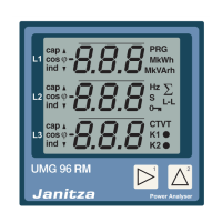
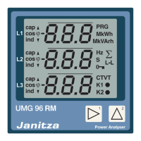
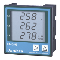
Illustrates and labels the front panel components of the device display.
Shows and labels the rear panel connections and symbols, including safety warnings.
Details the information presented on the device's rating plate.
Specifies installing the device in stationary, weather-protected front panels for air circulation.
Provides cut-out dimensions and ventilation distance requirements for installation.
Describes the procedure for fastening the device using snap-on mounting brackets.
Explains network types (TN, TT) and rated voltages according to DIN EN 61010-1/A1.
Lists rated voltages and circuit diagrams for three-phase 4-conductor networks.
Advises providing a suitable disconnector for the supply voltage for de-energizing the device.
Explains the requirement for supply voltage and connection via plug-type terminals.
Details voltage measurement inputs, potential dangers, and connection requirements.
Describes voltage measurement inputs for low-voltage networks and overvoltage categories.
Explains the device's requirement for mains frequency and its range (45-65 Hz).
Illustrates connection versions for three-phase 4-conductor and single-phase 3-conductor systems.
States the device is approved for current measurement using current transformers only.
Shows connection diagrams for current measurement in different network configurations.
Explains summation current measurement via two current transformers.
Describes connecting an ammeter in series to the UMG for current measurement.
Details common connection methods for PC communication using GridVis software.
Describes the RS485 interface, cable type, and connection capacity.
Provides guidelines for grounding and connecting cable shields for interface connections.
Explains the need for termination resistors at the start and end of RS485 segments.
Illustrates and explains bus structure, addressing, segment capacity, and repeaters.
Details Modbus RTU communication, setting ranges, functions, and transmission parameters.
Describes the isolated digital output for energy values and its S0 interface.
Explains how the device sends pulses for energy amounts and configuration settings.
Provides a schematic diagram for connecting the pulse output.
Explains how to specify the pulse value based on connected load and desired pulse rate.
Details pulse length settings and pulse pause characteristics.
Guides on establishing pulse length and calculating the pulse value.
Describes device operation via liquid crystal display and two keys, distinguishing display and programming modes.
Illustrates button functions for display mode (scrolling) and programming mode (navigation).
Explains how to access parameters for device configuration via serial interface or keys.
Shows an example of the device display for parameter addresses within an RS485 bus structure.
Describes measured value display profiles and automatic display change options.
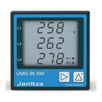
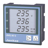
Illustrates an example of measured voltage display, showing L-N voltages and output status.
Instructs to connect supply voltage, check display, and observe safety precautions.
Explains the device has a programming mode for setting current transformer, voltage transformer, and parameters.
Details how to program a user password to prevent accidental changes to configuration data.
Instructs to configure current and voltage transformer ratios for accurate measurements.
Provides a step-by-step guide for programming the primary and secondary current transformer ratios.
Offers a step-by-step guide for programming the primary and secondary voltage transformer ratios.
Guides on accessing and programming parameter addresses, including device address and baud rate.
Explains setting the unique device address for master/slave networks.
Details setting the baud rate (e.g., 9.6, 19.2, 38.4 kbps) for RS485 communication.
Explains setting averaging times for current, power, and voltage measurements.
Describes how to delete minimum and maximum measured values from the device.
Refers to detailed description of display profiles and automatic changeover settings.
Explains activating and deactivating password protection and password entry.
Instructs on collectively deleting active, apparent, and reactive energy counter contents.
Explains LCD contrast settings for optimal viewing direction.
Describes the device's serial number display and its relation to the rating plate.
Explains how the device software (firmware) status is identified.
States the device has energy counters for active, apparent, and reactive energy.
Shows how active energy is displayed, including examples and units.
Defines harmonics and explains the device's requirement for mains frequency.
Explains how the device displays phase sequence and frequency, and how rotation fields are indicated.
Describes the operating hours counter that measures device recording time.
Details connecting supply voltage, checking the display, and verifying voltage range.
Explains connecting voltages above 300 VAC via transformer and checking displayed values.
Details connecting current transformers, noting short-circuiting outputs and checking ranges.
Instructs to check the rotating field direction in the device's measured value display.
Explains how to verify correct phase conductor assignment to the current transformer.
Guides on checking power measurement by short-circuiting current transformer outputs.
Confirms correctly connected inputs produce accurate individual and sum power calculations.
Details checks for correct phase conductor assignment and power display signs.
Advises comparing device-measured sum powers with active and reactive power counters.
Explains how measured values are sorted into profiles and appear one by one when a key is pressed.
Describes setting an automatically changing measured value display by programming a changeover time.
Highlights GridVis software's utility for configuring measured value displays and change profiles.
Provides a comprehensive overview of measured values organized into three display profiles.
Presents an overview of automatic display change profiles, noting they depend on changeover time.
Illustrates a connection example for the UMG 96-S2 device, showing power, measurement, and communication.
States that repair and calibration may only be carried out by the manufacturer.
Provides instructions for cleaning the front film and display using soft cloths and approved cleaners.
Mentions devices are pre-adjusted and readjustment is not necessary under normal conditions.
Explains firmware updates are executed using the GridVis® software.
Advises contacting the manufacturer for questions not covered in the manual, providing required information.
Describes warning errors that can be acknowledged and do not stop measurements.
Indicates serious errors that require sending the device to the manufacturer for inspection.
Explains how the device may recognize error causes and report them via error codes.
Defines measurement range exceedance and describes how it is indicated on the display.
Explains the coded error description format for measurement range exceedance parameters.
Provides a table of possible errors, their causes, and recommended remedies.
Lists general technical data including weight, impact resistance, and packaging details.
Provides information on free fall, temperature, and relative humidity for transport and storage.
Specifies operating temperature, humidity, altitude, and installation requirements.
Details nominal and operating ranges for supply voltage, power consumption, and fuses.
Lists specifications for voltage measurement, including category, surge, ranges, and resolution.
Specifies rated current, metering range, exceedance, resolution, and overvoltage category.
Lists specifications for the RS485 Modbus RTU/slave interface, including speeds.
Details specifications for the digital output, including switching voltage, current, and pulse frequency.
Specifies conductor sizes, sleeves, torque, and stripping length for supply voltage terminals.
Specifies conductor sizes, sleeves, torque, and stripping length for voltage measurement terminals.
Specifies conductor sizes, sleeves, torque, and stripping length for current measurement terminals.
Specifies conductor sizes, sleeves, torque, and stripping length for digital interface terminals.
Lists functions, symbols, accuracy classes, metering ranges, and display ranges for various measurements.
Explains the parameter list for operation settings and Modbus list for measured values.
Provides a detailed list of parameters, their addresses, formats, units, ranges, and default settings.
Lists Modbus addresses for frequently required measured values, including format, unit, and remarks.
Specifies number formats (short, ushort, int, uint, float) with size, minimum, and maximum values.
Provides notes on saving measured values in non-volatile memory and immediate saving of config data.
Presents dimensional drawings of the device from rear, side, and bottom views, including cut-out size.
| Device Type | Power Quality Analyzer |
|---|---|
| Measurement Category | CAT III 600 V |
| Mounting | DIN Rail |
| Protocols | Modbus RTU, Modbus TCP |
| Display | LCD |
| Accuracy | Class 0.5 |
| Operating Temperature | -10°C to +55°C |
| Weight | Approx. 300 g |
| Current Input | 5 A or 1 A |
| Power Measurement | Active, Reactive, Apparent |
| Energy Measurement | Active, Reactive |
| Frequency Measurement | 45-65Hz |
| Harmonics Analysis | Up to 40th harmonic |
| Communication Interfaces | RS485 |
| Dimensions | 96 x 96 x 60 mm |

