Do you have a question about the janitza UMG 509-PRO and is the answer not in the manual?
Covers disclaimer, copyright, changes, manual info, and symbols.
Procedures for returning defective units and proper disposal methods.
Explains warning notices, hazard levels, and general product safety.
Details risks and precautions when operating electrical devices.
Defines requirements for personnel working on electrical equipment.
Covers warranty voidance and specific safety for current transformers.
Provides guidelines for safe handling and disposal of batteries.
Describes the device, inspection process, and its intended applications.
Lists the general and measurement specifications of the device.
Outlines compliance with regulatory standards and declarations.
Details items included in the package and optional accessories.
Explains measurement techniques and device operation methods.
Introduces the software for device programming and data analysis.
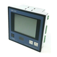
Describes the layout and components of the device's front panel.
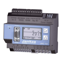
Details the connections and ports on the rear of the device.
Covers suitable installation sites, orientation, and fastening methods.
Explains connection for 3-phase, 3-conductor systems.
Explains connection for 3-phase, 4-conductor systems.
Lists suitable nominal network voltages for the device.
Presents various methods for connecting the device to a PC.
Covers essential installation steps for grounding, protection, and power.
Details the voltage measurement inputs and connection methods.
Explains current measurement via transformers and safety precautions.
Provides circuit diagrams for different voltage measurement configurations.
Shows circuit diagrams for various current measurement setups.
Illustrates connection diagrams for the auxiliary input.
Explains RCM capabilities, connections, and failure detection.
Demonstrates safe insulation for residual current transformer connections.
Explains temperature sensor connections and safe insulation practices.
Provides guidelines for proper cable shielding and grounding.
Covers RS-485 connection and termination resistor setup.
Explains Profibus connection and bus line setup.
Illustrates the general bus structure and connection principles.
Details the Ethernet connection, settings, and LEDs.
Describes the device's digital inputs and their signal detection.
Explains how to connect S0 pulse generators to digital inputs.
Covers the device's digital outputs, their isolation, and usage.
Lists button functions and describes the default 'Home' screen.
Explains how to navigate between main and by-value displays.
Guides users on how to select different measuring displays.
Details accessing extra data and clearing recorded values.
Describes how to view and analyze recorded transient events.
Explains how to access and interpret event logs for limit violations.
Guides on changing the device's display and menu language.
Covers configuration of IP address, netmask, and gateway settings.
Details Modbus protocol, device address, and baud rate.
Covers configuration for transformers, transients, events, frequency, and sensors.
Explains configuration of current and voltage transformer ratios.
Details settings for detecting and recording transient events.
Covers configuration for event recording and limit violations.
Allows setting mains frequency and selecting temperature sensor types.
Explains how to set or change the device access password.
Covers resetting energy meters, min/max values, and delivery condition.
Covers adjusting display brightness, standby settings, and screen saver.
Guides on selecting colors for graphical visualizations.
Explains unlocking functions and checking Jasic program status.
Details PTP setup and key Modbus parameters for synchronization.
Covers connecting supply voltage and verifying measured voltage readings.
Explains frequency determination and checking phase sequence.
Details connecting and verifying measured current inputs.
Shows voltage/current phasor diagrams and residual current connection.
Covers RCM monitoring and interpretation of alarm states.
Covers overrange conditions, power checks, and communication counter reset.
Details Modbus RTU protocol and transmission parameters for RS-485.
Explains Profibus profiles, device master file, and variable definition.
Describes preconfigured recording profiles and software customization.
Covers configuration of digital inputs and outputs using GridVis® software.
Shows a summary of key measured values per phase.
Provides extensive information on voltage, current, power, and peripherals.
Explains using charts for displaying current and historical measurements.
Displays instantaneous RCM values and limit settings.
Allows graphical representation of recorded events like overcurrent.
Shows graphical representation of transients within a date list.
Provides access to power quality status according to standards like IEC 61000-2-4.
Explains how to install and use additional applications like Push Service.
Guides to device information, display settings, and download area.
Covers essential maintenance tasks like repairs, cleaning, and adjustment.
Recommends recalibration frequency and details the firmware update process.
Explains how to replace the device's internal battery.
Provides general specifications, storage, and operating environmental data.
Lists electrical specifications for the device's power supply.
Details the technical specifications for voltage and current measurements.
Provides technical data for residual current monitoring.
Lists technical specifications for temperature sensor inputs.
Details technical specifications for digital I/O ports.
Lists technical specifications for RS-485, Profibus, and Ethernet interfaces.
Outlines the measurement accuracy and performance of device functions.
Shows the physical dimensions of the device.
Illustrates the structure of the device's configuration menu.
Shows the navigation paths for various measuring display screens.
| Device Type | Power Quality Analyzer |
|---|---|
| Power Measurement | Active, Reactive, Apparent Power |
| Energy Measurement | Active, Reactive, Apparent Energy |
| Operating Temperature | -10 °C to +55 °C |
| Frequency Measurement | 45 - 65 Hz |
| Communication Interfaces | Ethernet, RS-485 |
| Data Storage | Internal memory |
| Display | LCD Display |
| Power Supply | 85 - 265 V AC, 50/60 Hz |
| Weight | 1.5 kg |
| Measurement Category | CAT III 600V, CAT IV 300V |
| Harmonics Analysis | Voltage and Current Harmonics up to 63rd Harmonic |