UMG 103-CBM www.janitza.com
48
"Periodic commands"
If the device receives periodic Modbus com-
mands for synchronization, there are different
scenarios.
Scenario "Command outside the capture
time":
· Summed intermediate values are set to 0
· The time is set to 0 (new relative zero point)
· There is no value calculation
Pulse
Time base
end
Capture time
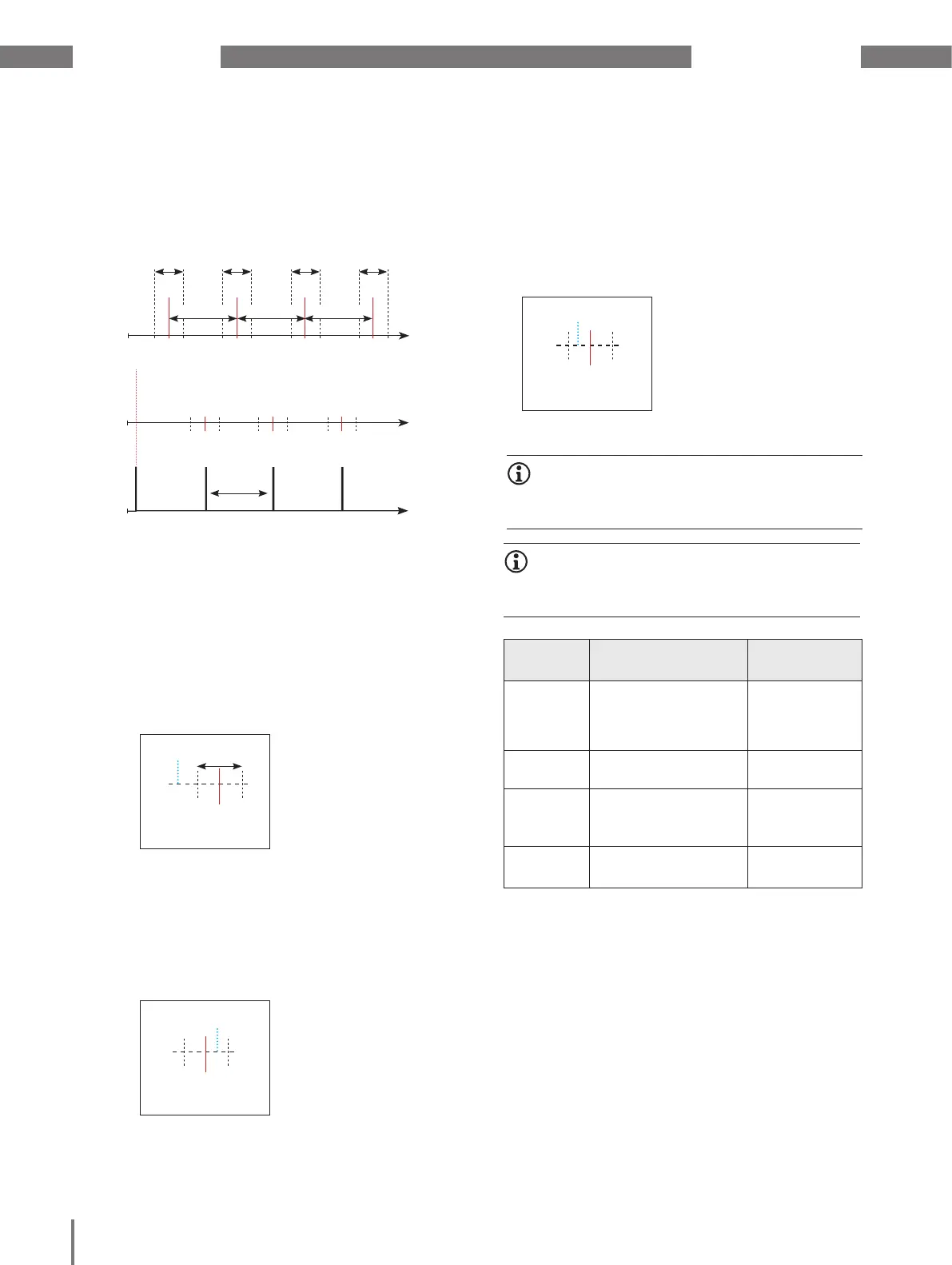
Scenario "Command according to time base,
but within the capture time"
· Summed intermediate values are set to 0
· The time is set to 0 (new relative zero point)
· There is no value calculation
Pulse
Time base
end
Scenario "Command before time base within
the capture time"
· Perform value calculation now
· The time is set to 0 (new relative zero point)
· Delete summed intermediate values
Pulse
Time base
end
INFORMATION
With periodic synchronization, the time is synchro-
nized with each command!
INFORMATION
The GridVis
®
software enables user-friendly config-
uration of the drag indicator functionality.
Modbus
address
Function Setting range
820 Set trigger flag for
drag indicator syn-
chronization
0 ...1
821 Time base in seconds 60 .. 65535
822 Enable flag of the
Modbus trigger
0 .. 1
823 Capture time in sec-
onds
0 .. 254
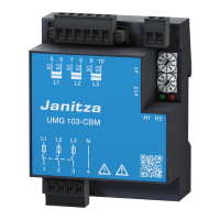
Fig.: Principle of synchronization with "Periodic
commands"
Capture time Capture time Capture time Capture time
Time base Time base Time base
Command history
Synchronization principle
Resynchronization
Relative
zero point
2 minutes
 Loading...