www.janitza.com UMG 103-CBM
43
10.3.2 Checking of voltage and current in-
puts by means of phasor diagram
The phasor diagram can be used to check incor-
rect connections at the voltage and current inputs.
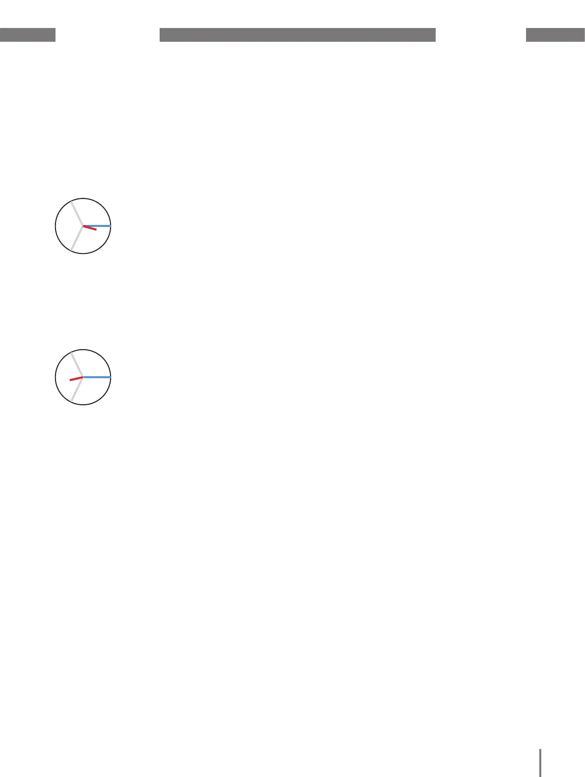
Example 1
Primarily ohmic load.
Voltage and current have
only a small deviation
in the phase position.
· The current measurement input is assigned to
the correct voltage measurement input
Example 2
Primarily ohmic load.
Voltage and current have
a deviation of about 180°
in the phase position.
· The measured current input is assigned to the
correct voltage measurement input.
· In the current measurement under consideration,
the connections k and I are reversed or there is a
feedback into the supply network.

 Loading...