Do you have a question about the janitza UMG 604-PRO and is the answer not in the manual?
Explanation of safety symbols and hazard warning levels used in the manual.
Essential precautions to prevent injury and damage when operating electrical devices.
Requirement for specialized personnel to operate and maintain the device.
Details on how the device continuously measures and calculates electrical variables.
Overview of different methods for programming and accessing measured values.
Information on using the GridVis software for device programming and data analysis.
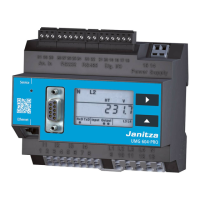
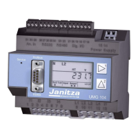
Key general and measurement features of the UMG 604-PRO device.
Requirement for a disconnector to safely disconnect the device from voltage.
Steps for connecting the device's power supply.
Requirements for measuring the network frequency.
Procedures for connecting voltage measurement inputs.
Checking the direction of the rotating field in the measured value indication.
Steps for connecting current measurement inputs.
Procedure for verifying power measurement accuracy.
Explanation of how to use the device's buttons for navigation and control.
How to navigate and view measured values in the default display mode.
Navigating and changing device settings via the programming menu.
Assigning current transformer ratios to individual measurement inputs.
Setting voltage transformer ratios for accurate voltage measurements.
Instructions for updating the device's firmware using GridVis software.
Specifications and connection requirements for the device's power supply.
| Device Type | Power Quality Analyzer |
|---|---|
| Power Measurement | Active, Reactive, Apparent Power |
| Data Logging | Yes |
| Operating Temperature | -10°C to +55°C |
| Storage Temperature | -20 °C to +70 °C |
| Measurement Category | CAT III 600V |
| Energy Measurement | Active, reactive, apparent energy |
| Frequency Measurement | 45 Hz to 65 Hz |
| Communication Interfaces | RS-485, Ethernet |
| Protocols | Modbus TCP, Modbus RTU |
| Display | LCD |
| Harmonics Analysis | Voltage and Current Harmonics up to 63rd harmonic |