UMG 103-CBM www.janitza.com
36
8.4 Bus structure
In a bus structure:
· Connect all devices in line according to the mas-
ter-slave principle.
· Each device has its own address.
· One segment contains up to 32 nodes/devices.
At the beginning and end of a segment, the cable
must be terminated with resistors (bus termina-
tion, 120 ohms, 1/4 W)!
· With more than 32 participants, use repeaters
(line amplifiers) to connect segments!
· Devices with bus termination switched on must
be powered.
· It is recommended that the master be placed at
the end of a segment. If the master is replaced
with the bus termination switched on, the bus is
out of operation.
· The bus can become unstable if a slave with bus
termination switched on is replaced or is de-en-
ergized.
· Devices that are not involved in the bus termina-
tion can be replaced without the bus becoming
unstable.
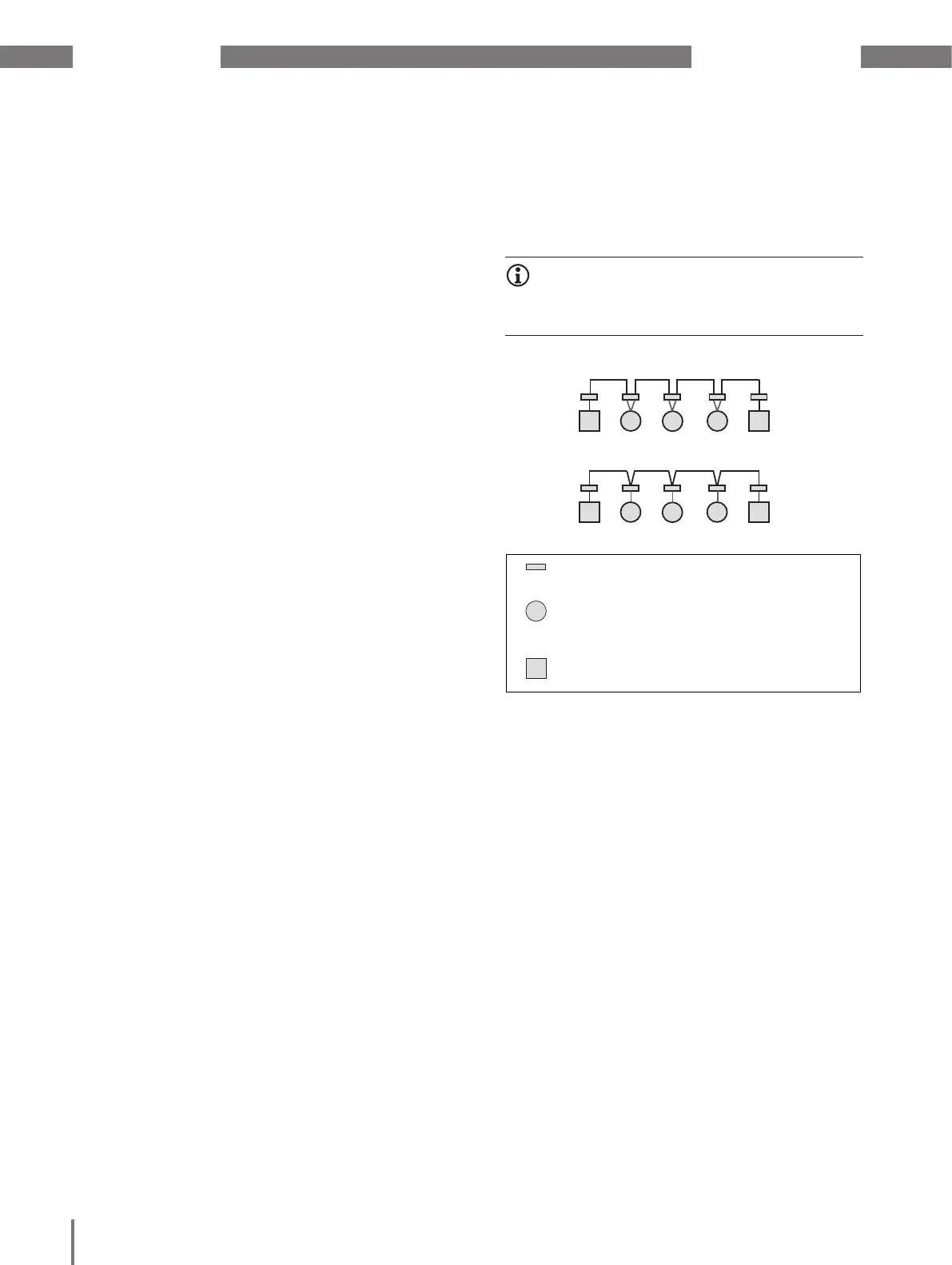
8.5 Termination resistors
At the beginning and end of a segment, the cable
is to be terminated with resistors (120 Ω, 1/4 W).
Right
Wrong
Terminal strip in the switchboard cabinet.
Device with RS-485 interface.
(Without termination resistor)
Device with RS-485 interface.
(With termination resistor on the device)
INFORMATION
The device does not contain an integrated termina-
tion resistor!
 Loading...