OPERATOR’S MANUAL · MIG/MAG PULSE SERIES
- 8 -
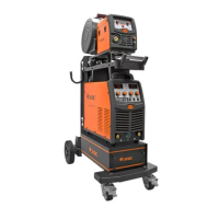
4. PANEL STRUCTURE AND SYMBOL DESCRIPTION
4.1 Panel structure(take MIG350P(N316) for example)
1) Power supply monitoring panel
2) Front panel
3) Parameter adjustment knob
4) Power output terminal “+”
5) Power output terminal “-”
6) Interface for the control cable
7) Back panel
8) Air switch
9) Fuse
10)
Socket for CO2 heater (applicable
to heater of 36V/120W)
11) Interface for the control cable
12) Water cooling/Air cooling switch
13) Power output terminal “+”
14) Power input cable
 Loading...