OPERATOR’S MANUAL · MIG/MAG PULSE SERIES
- 10 -
5. CONTROL PANEL
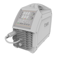
5.1 Power supply monitoring panel(take MIG400P(N317) for example)
Figure 5.1: Sketch map of the power supply monitoring panel
1. Welding mode selecting zone;
2. Current column parameters selecting zone;
3. Current column parameters display window;
4. Abnormity indicator;
5. Voltage column parameters display window;
6. Voltage column parameters selecting zone;
7. Welding process parameters selecting zone;
8. Operation mode selecting zone;
9. Gas-check zone;
10. Channel key;
11. Base metal selecting zone;
12. Gas selecting zone;
13. Wire diameter selecting zone;
14. Parameter adjustment knob.
 Loading...