11
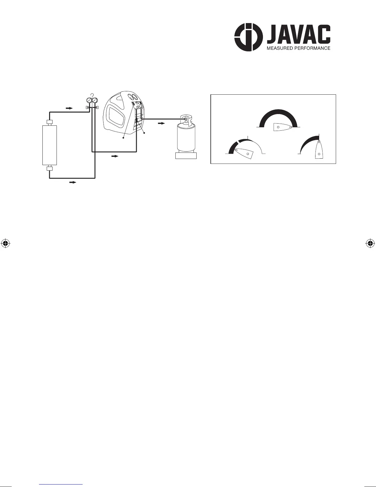
RECOVERY UNIT
POWER
SOURCE
OPTIONAL
CONNECTION
TO SYSTEM
CYLINDER
WITH
CT-OFD
SCALE
VAPOUR LIQUID
RECOVERY UNIT
VAPOUR
VAPOUR
LIQUID
SYSTEM
POWER
SOURCE
FILTER
CYLINDER
WITH
CT-OFD
SCALE
LIQUID
RECOVERY UNIT
LIQUID
CYLINDER
SCALE
POWER
SOURCE
RECOVERY UNIT
VAPOUR
LIQUID
LIQUID
SYSTEM
CYLINDER
WITH
CT-OFD
SCALE
POWER
SOURCE
FILTER
VALVE POSITIONS FOR PUSH/PULL METHOD
V2
L
I
Q
U
I
D
OPEN CLOSEPURGE
PURGE RECOVER
OPEN
V3
V1
VALVE POSITIONS DURING PURGE OPERATION
V2
L
I
Q
U
I
D
V1
CLOSE
OPEN
CLOSEPURGE
PURGERECOVER
OPEN
V3
VALVE POSITIONS DURING SUB-COOLING METHOD
V2
L
I
Q
U
I
D
V1
CLOSE
OPEN
CLOSEPURGE
PURGE RECOVER
OPEN
V3
VALVE POSITIONS DURING NORMAL RECOVERY
V2
L
I
Q
U
I
D
V1
CLOSE
OPEN
CLOSEPURGE
PURGERECOVER
OPEN
V3
RECOVERY UNIT
POWER
SOURCE
OPTIONAL
CONNECTION
TO SYSTEM
CYLINDER
WITH
CT-OFD
SCALE
VAPOUR LIQUID
RECOVERY UNIT
VAPOUR
VAPOUR
LIQUID
SYSTEM
POWER
SOURCE
FILTER
CYLINDER
WITH
CT-OFD
SCALE
LIQUID
RECOVERY UNIT
LIQUID
CYLINDER
SCALE
POWER
SOURCE
RECOVERY UNIT
VAPOUR
LIQUID
LIQUID
SYSTEM
CYLINDER
WITH
CT-OFD
SCALE
POWER
SOURCE
FILTER
VALVE POSITIONS FOR PUSH/PULL METHOD
V2
L
I
Q
U
I
D
OPEN CLOSEPURGE
PURGE RECOVER
OPEN
V3
V1
VALVE POSITIONS DURING PURGE OPERATION
V2
L
I
Q
U
I
D
V1
CLOSE
OPEN
CLOSEPURGE
PURGERECOVER
OPEN
V3
VALVE POSITIONS DURING SUB-COOLING METHOD
V2
L
I
Q
U
I
D
V1
CLOSE
OPEN
CLOSEPURGE
PURGE RECOVER
OPEN
V3
VALVE POSITIONS DURING NORMAL RECOVERY
V2
L
I
Q
U
I
D
V1
CLOSE
OPEN
CLOSEPURGE
PURG
ECOVER
OPEN
V3
SET-UP PROCEDURE FOR NORMAL REFRIGERANT RECOVERY
5.2.2 Switch o the power to the unit being serviced. If the power switch is in a remote location, LOCK
it out so that no one will accidentally turn it back on.
5.2.3 Make sure that the discharge hose from the recovery unit to the Recovery Cylinder is attached
to the LIQUID PORT. If cylinder contains refrigerant, partially open liquid valve and purge hose from
recover unit discharge port end. If cylinder is empty and pre–evacuated, refer to section 5.2.4.4 and
use incoming refrigerant to purge discharge hose from cylinder port end. Open cylinder liquid valve fully
after purging hose.
5.2.4 Set the rocovery unit for RECOVERY.
5.2.4.1 OPEN DISCHARGE valve (V3) to its fully open position.
5.2.4.2 SET PURGE/RECOVERY valve (V2) to RECOVERY position.
5.2.4.3 Open the Manifold Gauge VAPOUR valve slowly and verify that no leaks are present. Open
vapour valve fully and partially open liquid valve. Do not attempt to recover 100% liquid.
5.2.4.4 At this point use incoming refrigerant to purge hose.
5.2.5 Switch ON the recovery unit and verify that the compressor is operating and cooling air is
exhausting from the back of the machine.
5.2.6 MONITOR the inlet pressure (LP, Low Pressure Gauge) and SLOWLY OPEN the recovery unit
INLET valve (V1) fully. If the compressor ‘knocks’ shut V1 immediately, then close manifold liquid valve.
Open V1 while the machine is running and continue to recover in vapour phase.
5.2.7 Continue to operate until the required VACUUM has been pulled on the system (refer to Section
10.0 of this Manual), as indicated by the LP gauge. Switch OFF the recovery unit, CLOSE the INLET
(V1), and wait for 5 minutes. If the Pressure in the system, as indicated on the Manifold Gauge, rises
above 0 Kpa, refrigerant is still present. If so, RESTART Recovery Machine, REOPEN the INLET (V1) and
run until the required VACUUM is reached again. Repeat this process until all the refrigerant is removed
resulting in a nal reading of 0 Kpa or less.
5.2.8 TERMINATE the RECOVERY operation.
5.2.8.1 CLOSE Manifold Gauge Liquid and Vapor valves.
5.2.8.2 CLOSE XTR-PRO-DV INLET Valve (V1).
5.2.8.3 Switch POWER OFF.
5.2.8.4 It is a good practice to purge the Recovery Machine after each use.
Refer to section 5.3 of this manual.
XTRC2A2L-JAV-1059-PRO-DV-safe-op-manual-A5-180pp.indd 11 10/01/2018 12:29
 Loading...