13
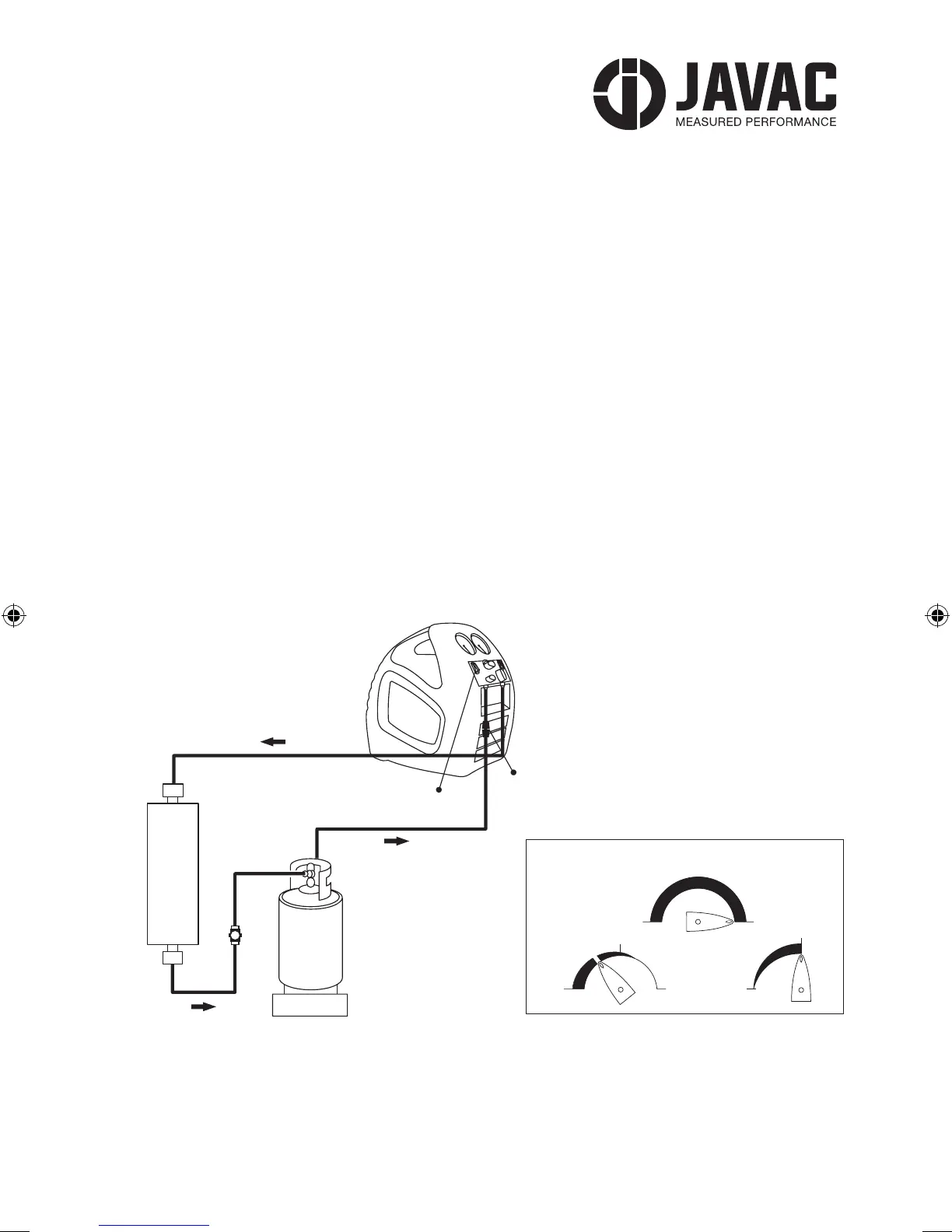
5.4 PUSH/PULL OPERATION
5.4.1 The PUSH PULL method is used to move a large amount of liquid refrigerant from the system
being serviced to the recovery cylinder without passing it through the compressor. This method is
only useful when more than 7 Kg of liquid is known to be in the system and it can be easily isolated.
DO NOT ATTEMPT the PUSH PULL process unless you are sure of the situation.
5.4.2 Connect the refrigerant hoses as shown below. Addition of a SIGHT GLASS in line between the
system being serviced and the recovery cylinder can be an important aid to determine when all the
liquid has been transferred and only vapour remains.
5.4.3 This process uses the PULL from the exhausted recovery cylinder and the Discharge PUSH
from the recovery unit to move the liquid refrigerant. Rates in excess of 5 Kg per minute can be
achieved by this procedure.
5.4.4 The SCALE is required in this process to ensure that the cylinder is not overlled. The cylinder
shuto switch, if used, would stop the compressor but could not guarantee that additional refrigerant
ow would cease because of the dynamics of the system, thus possibly overlling the cylinder.
SET-UP PROCEDURE FOR PUSH/PULL METHOD
RECOVERY UNIT
POWER
SOURCE
OPTIONAL
CONNECTION
TO SYSTEM
CYLINDER
WITH
CT-OFD
SCALE
VAPOUR LIQUID
RECOVERY UNIT
VAPOUR
VAPOUR
LIQUID
SYSTEM
POWER
SOURCE
FILTER
CYLINDER
WITH
CT-OFD
SCALE
LIQUID
RECOVERY UNIT
LIQUID
CYLINDER
SCALE
POWER
SOURCE
RECOVERY UNIT
VAPOUR
LIQUID
LIQUID
SYSTEM
CYLINDER
WITH
CT-OFD
SCALE
POWER
SOURCE
FILTER
VALVE POSITIONS FOR PUSH/PULL METHOD
V2
L
I
Q
U
I
D
OPEN CLOSEPURGE
PURGE RECOVER
OPEN
V3
V1
VALVE POSITIONS DURING PURGE OPERATION
V2
L
I
Q
U
I
D
V1
CLOSE
OPEN
CLOSEPURGE
PURGERECOVER
OPEN
V3
VALVE POSITIONS DURING SUB-COOLING METHOD
V2
L
I
Q
U
I
D
V1
CLOSE
OPEN
CLOSEPURGE
PURGE RECOVER
OPEN
V3
VALVE POSITIONS DURING NORMAL RECOVERY
V2
L
I
Q
U
I
D
V1
CLOSE
OPEN
CLOSEPURGE
PURGERECOVER
OPEN
V3
RECOVERY UNIT
POWER
SOURCE
OPTIONAL
CONNECTION
TO SYSTEM
CYLINDER
WITH
CT-OFD
SCALE
VAPOUR LIQUID
RECOVERY UNIT
VAPOUR
VAPOUR
LIQUID
SYSTEM
POWER
SOURCE
FILTER
CYLINDER
WITH
CT-OFD
SCALE
LIQUID
RECOVERY UNIT
LIQUID
CYLINDER
SCALE
POWER
SOURCE
RECOVERY UNIT
VAPOUR
LIQUID
LIQUID
SYSTEM
CYLINDER
WITH
CT-OFD
SCALE
POWER
SOURCE
FILTER
VALVE POSITIONS FOR PUSH/PULL METHOD
V2
L
I
Q
U
I
D
OPEN CLOSEPURGE
PURGE RECOVER
OPEN
V3
V1
VALVE POSITIONS DURING PURGE OPERATION
V2
L
I
Q
U
I
D
V1
CLOSE
OPEN
CLOSEPURGE
PURGERECOVER
OPEN
V3
VALVE POSITIONS DURING SUB-COOLING METHOD
V2
L
I
Q
U
I
D
V1
CLOSE
OPEN
CLOSEPURGE
PURGE RECOVER
OPEN
V3
VALVE POSITIONS DURING NORMAL RECOVERY
V2
L
I
Q
U
I
D
V1
CLOSE
OPEN
CLOSEPURGE
PURGERECOVER
OPEN
V3
XTRC2A2L-JAV-1059-PRO-DV-safe-op-manual-A5-180pp.indd 13 10/01/2018 12:29