EasyManua.ls Logo

Jaycar QM1528 - User Manual

Jaycar QM1528
20 pages
Print Icon
To Next Page IconTo Next Page
Loading...
Operating Instruction for
Autoranging Digital
Multimeter
Please read this manual before switching the unit on.
Important safety information inside.
Question and Answer IconNeed help?

Do you have a question about the Jaycar QM1528 and is the answer not in the manual?

Overview

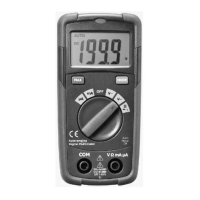
This document describes the Jaycar Autoranging Digital Multimeter, a handheld device designed for various electrical measurements.

Function Description

The multimeter is capable of measuring:

  • DC Voltage (VDC): Ranges from 200.0mV to 600V.
  • AC Voltage (VAC): Ranges from 2.000V to 600V (50 to 60Hz).
  • DC Current (DC): Ranges from 200.0µA to 200.0mA.
  • AC Current (AC): Ranges from 200.0µA to 200.0mA.
  • Resistance (Ω): Ranges from 200.0Ω to 20.00MΩ.
  • Continuity Check: Indicates continuity with an audible signal if resistance is less than approximately 100Ω.
  • Diode Test: Measures the forward voltage of a diode.

The device features an autoranging function, which automatically selects the appropriate measurement range. It also includes a MAX Hold function to capture and display the maximum measured value.

Important Technical Specifications

General Specifications

  • Display: 2000 count LCD display with function indication.
  • Polarity: Automatic, (-) negative polarity indication.
  • Overrange Indication: "OL" mark indication.
  • Low Battery Indication: The " " symbol is displayed when the battery voltage drops below the operating level.
  • Measurement Rate: 2 times per second, nominal.
  • Auto Power Off: Meter automatically shuts down after approximately 15 minutes of inactivity.
  • Operating Environment: 0 to 50°C (32 to 122°F) at <70% relative humidity.
  • Storage Temperature: -20 to 60°C (-4 to 140°F) at <80% relative humidity.
  • Max Height: 2000m.
  • Pollution Degree: 2.
  • Power: One 12V battery.
  • Dimensions (H x W x D): 108 x 53 x 32mm.
  • Weight: Approximately 102g.
  • Safety Compliance: EN61010-1.
  • Insulation: Class 2, Double insulation.
  • Overvoltage Category: CAT III 300V / CAT II 600V.

Input Limits

  • VDC or VAC: 600V DC/AC.
  • mA DC/AC: 200mA DC/AC.
  • Resistance, Diode Test, Continuity: 250V DC/AC.

Accuracy (Accuracy is given at 18 to 28°C (65 to 83°F), less than 70%RH)

  • DC Voltage:
    • 200.0mV: ±(0.5% + 4 digits)
    • 2.000V, 20.00V, 200.0V: ±(1.2% + 5 digits)
    • 600V: ±(1.5% + 5 digits)
    • Input Impedance: 10MΩ. Maximum Input: 600V AC/DC rms.
  • AC Voltage (50 to 60Hz):
    • 2.000V, 20.00V: ±(1.2% + 4 digits)
    • 200.0V: ±(1.5% + 3 digits)
    • 600V: ±(2.0% + 4 digits)
    • Input Impedance: 10MΩ. Maximum Input: 600V AC/DC rms.
  • DC Current:
    • 200.0µA, 2000µA: ±(1.0% + 3 digits)
    • 20.00mA, 200.0mA: ±(1.5% + 3 digits)
    • Overload Protection: 0.2A/600V. Maximum Input: 200mA DC or 200mA AC rms on µA/mA ranges.
  • AC Current:
    • 200.0µA, 2000µA: ±(1.5% + 3 digits)
    • 20.00mA, 200.0mA: ±(1.8% + 3 digits)
    • Overload Protection: 0.2A/600V. Maximum Input: 200mA DC or 200mA AC rms on µA/mA ranges.
  • Resistance:
    • 200.0Ω: ±(1.5% + 4 digits)
    • 2.000KΩ, 20.00KΩ: ±(1.2% + 2 digits)
    • 200.0KΩ, 2.000MΩ: ±(1.5% + 2 digits)
    • 20.00MΩ: ±(2.0% + 3 digits)
    • Input Protection: 250V DC or 250V AC rms.
  • Diode Test:
    • Test Current: 0.3mA typical. Open circuit voltage: 1.5V DC typical.
    • Resolution: 1mV. Accuracy: ±(1.0% + 5 digits).
    • Overload Protection: 250V AC/DC rms.
  • Continuity:
    • Audible threshold: Less than 100Ω. Test current: <0.3mA.
    • Overload protection: 250V AC/DC rms.

Usage Features

Meter Description

  1. NCV Indicate Lamp: Non-Contact Voltage indicator.
  2. 2000 Count Liquid Crystal Display: Shows measurement readings and symbols.
  3. MAX Hold Button: Used to hold the maximum measured value.
  4. MODE Button: Selects Diode/Continuity or DC/AC current functions.
  5. Function Switch: Rotary switch to select measurement functions (OFF, mA, V~, V, Ω, µA).
  6. COM Input Jack: Common input terminal for the black test lead.
  7. Positive Input Jack: Positive input terminal for the red test lead.
  8. Battery Cover: Access for battery replacement.

Symbols Used on LCD Display

  1. Autoranging: Indicates the meter is in autoranging mode.
  2. Diode Test: Symbol for diode testing.
  3. Continuity: Symbol for continuity check.
  4. Maximum: Indicates MAX Hold function is active.
  5. Battery Status: Shows battery charge level.
  6. Units of Measure List: Displays units like KΩ, MΩ, V, mV, µA, mA.
  7. Measurement Reading: The numerical value of the measurement.
  8. Minus Sign: Indicates negative polarity.
  9. Alternating Current: Indicates AC measurement.
  10. Direct Current: Indicates DC measurement.

Operation

  • Safety First: Always observe maximum personal safety during operation. Do not use the meter if damaged, or if you suspect it is not operating properly. Never ground yourself when taking electrical measurements. Do not touch exposed metal pipes, outlets, fixtures, etc., which might be at ground potential. Keep your body isolated from ground by using dry clothing, rubber shoes, rubber mats, or any approved insulating material. Turn off power to the circuit under test before cutting, unsoldering, or breaking the circuit. Use caution when working above 60V DC or 30V AC rms, as such voltages pose a shock hazard. When using probes, keep your fingers behind the finger guards. Measuring voltage which exceeds the limits of the multimeter may damage the meter and expose the operator to a shock hazard. Never apply voltage or current to the meter that exceeds the specified maximum.
  • Auto Power Off: The meter automatically shuts off after 15 minutes of inactivity when the function switch is in the OFF position.
  • "OL" Indication: If "OL" appears on the display, the value exceeds the range, and a higher range should be selected.
  • Low Voltage/Current Readings: On some low AC and DC voltage ranges, with the test leads not connected to a device, the display may show a random, changing reading. This is normal and is caused by high-input sensitivity; the reading will stabilize and give a proper measurement when connected to a circuit.

Measurement Procedures

  • DC Voltage Measurement:
    1. Set the function switch to the VDC position.
    2. Insert the black test lead into the COM Input Jack and the red test lead into the Positive Input Jack.
    3. Touch the test probe tips to the circuit under test, observing correct polarity.
    4. Read the voltage on the display.
  • AC Voltage Measurement:
    1. Set the function switch to the VAC position.
    2. Insert the black test lead into the COM Input Jack and the red test lead into the Positive Input Jack.
    3. Touch the test probe tips to the circuit under test, observing correct polarity.
    4. Read the voltage on the display.
  • DC Current Measurement:
    1. For current measurements up to 2000µA DC, set the function switch to the µA Position. For current measurements up to 200mA DC, set the function switch to the mA Position.
    2. Insert the black test lead into the COM Input Jack and the red test lead into the Positive Input Jack.
    3. Press the MODE Button until "DC" appears in the display.
    4. Remove power from the circuit under test, then open up the circuit at the point where you wish to measure current.
    5. Touch the black test probe tip to the negative side of the circuit; Touch the red test probe tip to the positive side of the circuit.
    6. Apply power to the circuit.
    7. Read the current in the display.
  • AC Current Measurement:
    1. For current measurements up to 2000µA AC, set the function switch to the µA Position. For current measurements up to 200mA AC, set the function switch to the mA Position.
    2. Insert the black test lead into the COM Input Jack and the red test lead into the Positive Input Jack.
    3. Press the MODE Button until "AC" appears in the display.
    4. Remove power from the circuit under test, then open up the circuit at the point where you wish to measure current.
    5. Touch the black test probe tip to the negative side of the circuit; Touch the red test probe tip to the positive side of the circuit.
    6. Apply power to the circuit.
    7. Read the current in the display.
  • Resistance Measurement:
    1. Set the function switch to the Ω position.
    2. Insert the black test lead into the COM Input Jack and the red test lead into the Positive Input Jack.
    3. Touch the test probe tips across the circuit or part under test. It is best to disconnect one side of the part under test so the rest of the circuit will not interfere with the resistance reading.
    4. Read the resistance in the display.
  • Continuity Check:
    1. Set the function switch to the Ω position.
    2. Insert the black test lead into the COM Input Jack and the red test lead into the Positive Input Jack.
    3. Press the MODE Button until the " " symbol appears in the display.
    4. Touch the test probe tips to the circuit or wire you wish to check.
    5. If the resistance is less than approximately 100Ω, the audible signal will sound, and the display will also show the actual resistance.
  • Diode Test:
    1. Set the function switch to the Ω position.
    2. Insert the black test lead into the COM Input Jack and the red test lead into the Positive Input Jack.
    3. Press the MODE Button until the " " symbol appears in the display.
    4. Touch the test probe tips to the diode or semiconductor junction you wish to test, note the meter reading.
    5. Reverse the probe polarity by switching probe position, note this reading.
    6. The diode or junction can be evaluated as follows:
      • If one reading shows a value and the other reading shows "OL", the diode is good.
      • If both readings show "OL", the device is open.
      • If both readings are very small or 0, the device is shorted.
    • Note: The value indicated in the display during the diode check is the forward voltage.

Maintenance Features

Replacing the Battery

  • Warning: To avoid electric shock, disconnect the test leads from any source of voltage before removing the battery door.
  • When the batteries become exhausted or drop below the operating voltage, " " will appear in the right-hand side of the LCD display, the battery should be replaced.
  • Follow instructions for installing battery.
  • Dispose of the old battery properly.
  • Procedure:
    1. Disconnect the test leads from the meter.
    2. Open the battery door by loosening the screw using a Phillips head screwdriver.
    3. Insert the battery into battery holder, observing the correct polarity.
    4. Put the battery door back in place. Secure with the two screws.
  • Warning: To avoid electric shock, do not operate the meter until the battery door is in place and fastened securely.
  • Note: If your meter does not work properly, check the fuses and battery to make sure that they are still good and that they are properly inserted.

Replacing the Fuses

  • Warning: To avoid electric shock, disconnect the test leads from any source of voltage before removing the fuse door.
  • Procedure:
    1. Disconnect the test leads from the meter and any item under test.
    2. Open the fuse door by loosening the screw on the door using a Phillips head screwdriver.
    3. Remove the old fuse from its holder by gently pulling it out.
    4. Install the new fuse into the holder.
    5. Always use a fuse of the proper size and value (0.2A/600V fast blow for the 200mA range).
    6. Put the fuse door back in place. Insert the screw and tighten it securely.
  • Warning: To avoid electric shock, do not operate your meter until the fuse door is in place and fastened securely.

Jaycar QM1528 Specifications

General IconGeneral
BrandJaycar
ModelQM1528
CategoryMultimeter
LanguageEnglish

Related product manuals