3
Connecting Your System JBL BASSTUBE BTX250
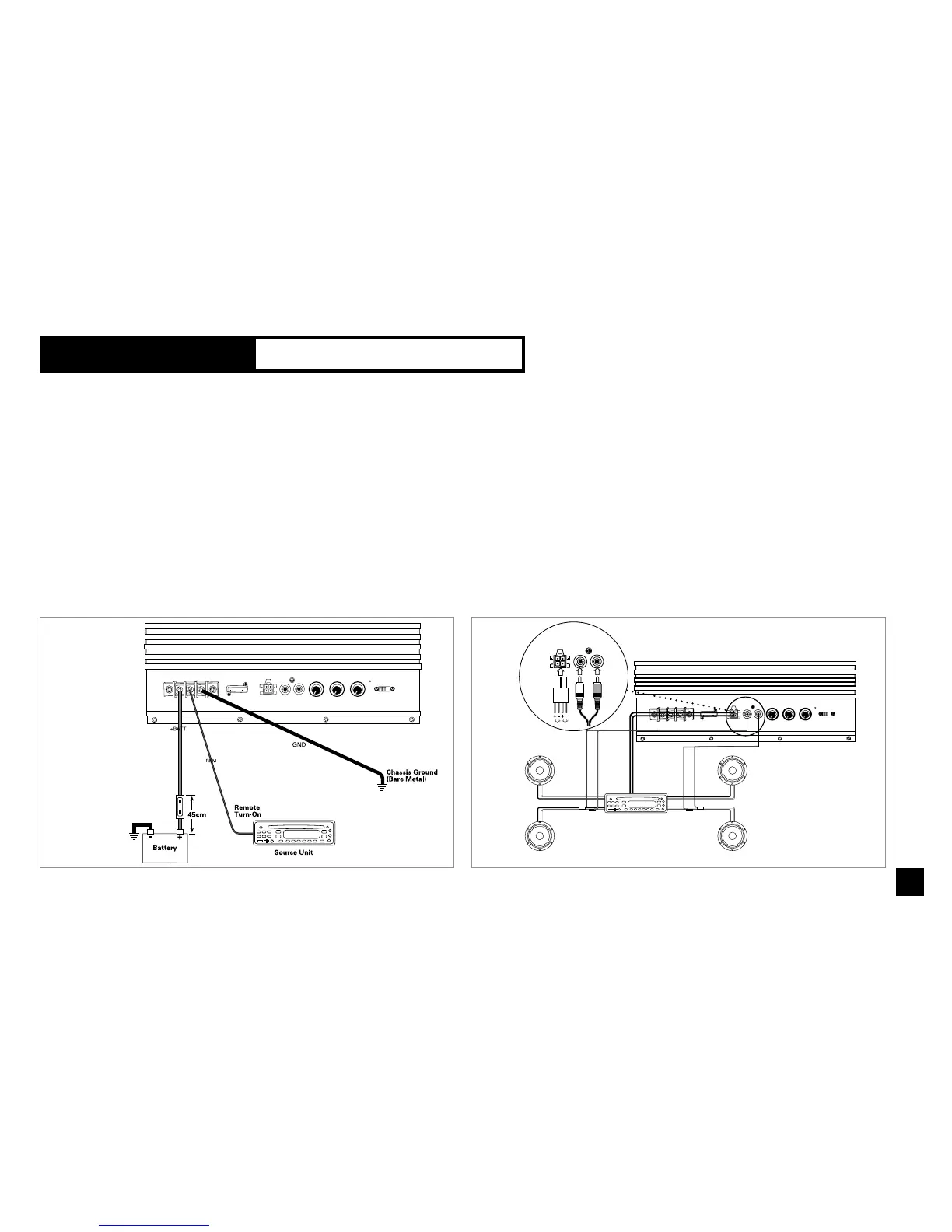
POWER-SUPPLY
CONNECTIONS
Figure 4. BTX250 connections and ter-
minals.
B+: Connect a wire (at least 4mm
2
)
between the vehicle’s + (positive) bat-
tery terminal and the "+BATT" terminal
on BTX250. You must install a fuse
holder with a 15A fuse within 50cm of
the battery. Route the power wire
through a grommet in the vehicle’s fire-
wall.
If there is no factory grommet
available, you must install one.
B–: Connect a wire (at least 4mm
2
)
between the "GND" terminal on
BTX250 and a bare metal surface near
the mounting location. You may need to
scrape away some paint from the metal
surface to insure a good connection.
Use a screw and a lock (star) washer.
Remote: Connect a wire between the
remote terminal on BTX250 and the
remote output wire on your head unit.
This wire should provide between
+5VDC and +12VDC when the head
unit is on and no voltage when the unit
is off.
INPUT CONNECTIONS
Note: BTX250 is equipped with two
line-level (RCA) inputs and two
speaker-level inputs.
Figure 5, Input connections
Head units with dedicated
subwoofer outputs (line-level):
Connect the subwoofer output from
the head unit to the line-level inputs.
Head units with two line-level out-
puts and two (or four) speaker-level
outputs: Connect the two line-level
outputs from the head unit to the line-
level input on BTX250. Or connect two
speaker-level outputs from the head
unit to the Universal Interface inputs on
BTX250, which correspond to the
linelevel inputs.
Note: The Universal Interface input
wiring harness included with BTX250
is color coded to correspond with the
speaker-level outputs of many after-
market head units and adapters sold
as accessories.