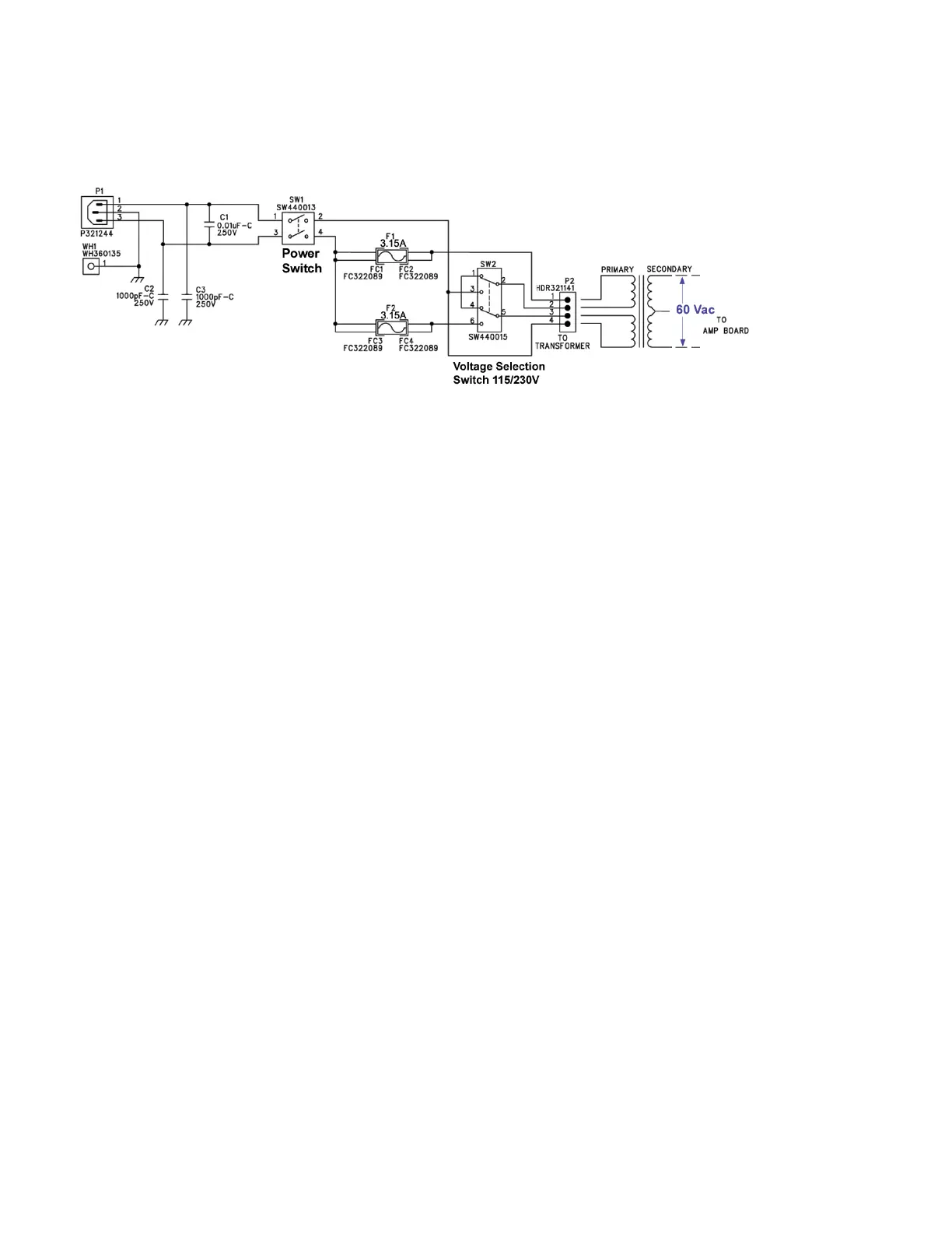
AC Input Module
The main line voltage is connected at input jack P1 on the ac input PCB. Capacitors C2 and C3 work
in conjunction with C1 to help reduce the instantaneous line voltage spikes that cause static noise in
the high frequency range. Pin 2, the AC ground, is connected to chassis ground. Pins 1 and 3 are
connected to the 2-pole 2-position main power switch, SW1. Toggling of SW1 directs the ac voltage to
travel through fuses, F1 and F2, to the voltage selector switch, SW2 that allows the customer to
manually select between 120V or 230V. It is important to power down the equipment before this
switch is operated to avoid possible driver damage. Electrically, this switch, SW2, determines which
power transformer primary receives the applied alternating current so that the proper output voltage
will result.
We will assume that the mains input voltage to the transformer is 115 Vac for this circuit description.
The toroidal transformer output would then deliver 60Vac to the power supply connector P3 on the
main amplifier PCB.

 Loading...