3. Initial start-up
When the device is switched on for the first time, the display language is selected and then the unit needs to be calibrated� It is not possible to call up
other menu items beforehand� This is for your own safety as the device would measure incorrect values without successful calibration� Afterwards,
any settings can be made�
If the value overview (chap� 4) appears instead of „Language selection“, the unit has already been used (demonstration etc�)� In this case calibration
must be carried out� To do this, tap the „Settings“ symbol and select the menu item „Calibration“� Confirm with OK� Continue as described below�
3.1 Preparation
Please use the calibration liquids and cuvettes supplied with the JBL PROFLORA CO₂ pH SENSOR SET� Fill each calibration cuvette up to the 10 ml
mark, filling one cuvette with pH 7�00 buer solution, one with pH 4�00 buer solution and one with deionised water (JBL PROFLORA CO₂ DEST)�
The buer solutions are coloured with an indicator to avoid confusion� For more stability, place the calibration cuvettes in the 3 large holes on the
calibration holder� Unscrew the screw fitting on the storage tube of the sensor by about one turn and pull out the sensor� Put the sensor and the
temperature sensor in the calibration cuvette filled with deionised water, sway both sensors a little and leave them there� Since the pH measurement
and the calibration are temperature-dependent, both sensors must always be immersed in the calibration liquid�
3.2 Language selection
Select your desired language by tapping the arrow symbols and confirm with OK� The following choices are available: DE/EN-UK/FR/NL/IT/DK/ES/PT/
RO�
3.3 Calibration
• Tap OK to start the calibration�
• Follow the instructions in the display panel and immerse both sensors into the appropriate buer solution, first in one solution and then the other�
The device guides you through a so-called two-point calibration� In this process, the device is first calibrated with buer solution pH 7�00 and
then with buer solution pH 4�00, never the other way round! The temperature is irrelevant because it is measured by the temperature sensor and
temperature influences are automatically compensated�
• After successful calibration, the display shows in this order: „Calibration, pH 7�00 OK“, „Calibration, pH 4�00 OK“�
• Confirm both with OK�
• Tap the settings symbol� The value overview appears, informing you about the most important values (chap� 4)�
• Dispose of the used buer solutions, briefly rinse the cuvettes in tap water and dry them
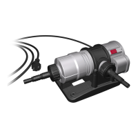
Install the pH sensor in a very dark place with good water flow in the aquarium� The sensor can be immersed to a maximum of 2/3 of its length� The
sensor cap with cable must not be immersed in the water� The suction holders provided allow the temperature sensor to be attached anywhere in the
aquarium� Now you can select your required settings on the menu (chap� 7�1 – 7�13)�
4. Sleep mode and value overview
If no input is made, the device will revert to the sleep mode after about 30 seconds� The image of a water drop and the permanent information of
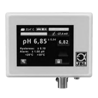
the current pH and temperature values will appear� After tapping the screen the value overview will appear� It gives information, as illustrated below,
about the most important processes relating to the pH value and the supply of CO₂ into the aquarium:
1 Switch field “Settings” (the way to all possible settings)
2 Status line Alarm with adjusted limit values for pH and temperature
3 Status line Hysteresis with adjusted value
4 Actual pH value (current pH value in buer or in your aquarium)
5 Status line Auto pH with adjusted KH
6 Current temperature (illustrated flashing read in the alarm status)
7 Valve status (illustrated in automatic mode with valve on continuity)
8 Time to calibration (days/hours)
9 Sensor voltage in mV
10 Current precision of measurement (re-calculated for each calibration)
11 pH set point (required pH value, adjusted by device through CO₂ supply)
12 Warning triangle (flashes in case of alarm, while the aected value flashing in red)
13 Key lock (unlocked in illustration)
5. pH set point adjustment
If you are using a pH control device for the first time, we strongly recommend that you initially use the auto pH menu point to adjust the pH set point:
Touch the switch field “Settings” and select the menu point “Auto pH” by tapping on the arrow symbols� Confirm with “OK”� Enter the current KH
value of your aquarium water by pressing the fields “plus” or “minus”� Confirm with “OK”� It is important you measure the KH level in your aquarium
by means of a KH test, such as the JBL PROAQUATEST KH�
The device will now calculate the optimal pH value for this KH and save it as set point� The calculation is based on a CO₂ content of 22�5 mg/l, which
is considered as optimal�
5.1 Control
When the valve is switched to automatic (factory setting, see chap� 7�7), the device adjusts the following:
Current actual value in the aquarium: pH 7�80� Auto pH has set pH 7�10 as set point� Symbol for valve status shows “open” and “A” for automatic�
CO₂ is now added until a pH value of 7�00* is attained� The device then closes the solenoid valve and the symbol for valve status shows “shut” and
“A” for automatic�
Consumption by the plants and the compensation from the atmosphere leads to the CO₂ level decreasing and the pH level slowly increasing� After
reaching pH 7�20* the solenoid valve opens again and CO₂ is added again, until the pH value has dropped again to 7�00*, and so on�
*For pre-selected hysteresis (switching point) of 0�1 (factory setting, see chap� 7�6)
UKUK
18 19
1
12
13
2
11
3
10
4
9
5
8
6
7
 Loading...