8.2 Return function
If no key is pressed for 30 seconds the display automatically returns to the value overview� Any values not confirmed by OK will not have been stored�
8.3 Sleep mode
If no key is pressed for 10 minutes, the display backlighting fades to the lowest setting� When you tap the display, it switches back to the previously
set brightness level�
8.4 Cleaning
The surface of the device may be cleaned with a soft, slightly damp cloth� Do not use cleaning agents� Do not immerse the device in water!
8.5 Power failure
In the event of a power failure, all the values previously set will remain stored� Only the time calculation for the calibration reminder is interrupted
during the power failure�
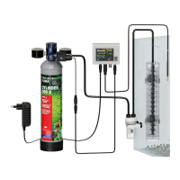
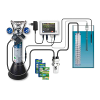
8.6 Use of JBL PROFLORA CO₂ CONTROL in combination with calcium reactors in marine water
Calcium reactors are tasked with dissolving the lime out of the substrate within the reactor (e�g� coral gravel), and returning it as carbonate hardness
into the marine water aquarium� Thus they counteract the consumption of KH in the aquarium and no KH supplements need to be added� The KH of
natural marine water in oceans is between 6 and 9 °dKH, depending on the ocean� CO₂ is the best way to eectively release KH from the substrate in
the calcium reactor� This process requires a pH level of approx� 6�5 inside the calcium reactor, which needs continuous monitoring�
For calcium reactors which have an opening for pH sensors, this is very easy:
All you have to do is install the pH sensor there and set the pH set point on the JBL PROFLORA CO₂ CONTROL to 6�5 (see chap� 7�4)� The connecting
cable for the solenoid valve needs to be connected to the solenoid valve of the CO₂ system, which introduces the CO₂ into the calcium reactor�
For calcium reactors without an opening for a pH sensor, the sensor has to be installed inside the water stream leaving the calcium reactor, by means
of a suitable device� Settings as described above�
9. Note on handling pH sensors
The pH sensor is the most delicate part of the whole measuring equipment and therefore needs special care when handling� If the following few
handling tips are followed, the sensor will provide accurate measurements for a long time�
9.1 Handling and care
• Avoid hard impacts and take particular care when handling the delicate sensor tip made of special glass�
• Avoid kinks in the sensor cable�
• Never allow the sensor tip to dry out!
• Sensors which are not in use for a longer period of time should always be placed in JBL storage solution�
• Never fully immerse the sensor in the water� The sensor cap and cable connection should always be out of the water� Ideally the sensor should be
immersed to the top of the writing on the sensor shaft (JBL pH Sensor)�
• Place the sensor in as dark a place as possible in the aquarium to prevent algae growing on the tip� Algae growth could lead to incorrect measure
-
ments
�
• Do not lay the sensor cable next to mains current-bearing cables for long distances�
• If the sensor is accidentally pulled out of the water or the water level drops significantly, the device will measure incorrectly and adjust accordingly�
This is dangerous for the fish� Regular checking is therefore recommended�
• Any dirt that has accumulated on the tip of the sensor can be carefully wiped o with a soft cloth� Never rub vigorously, just dab�
9.2 Service life of the sensor
pH sensors are subject to natural wear and tear, also known as ageing� Ageing begins from the day of manufacture� The voltage delivered by the
sensor tip and recorded by the measuring device and transformed into pH units gives an indication of the condition of the sensor� The voltage in mV
(millivolt) can be read directly from the JBL PROFLORA CO₂ CONTROL�
When dipped into pH 7�00 buer solution, a new sensor shows a voltage of 0 +/- a few mV� This voltage changes per full pH unit by about 59 mV in
a positive or negative direction, depending on whether measurements are above or below 7�00� When a new sensor is dipped into pH 4�00 buer
solution, the voltage is approx� 177 mV� If the sensor has aged, voltage measured at pH 7�00 usually shifts into the negative range�
For example, in 7�00 buer solution, -28 mV is measured� In addition, the voltage dierence per full pH unit decreases� For example, for pH 4�00
buer solution, 110 mV can still be indicated, which would correspond to a dierence of 46 mV per pH unit� For pH 7�00 the JBL PROFLORA CO₂
CONTROL accepts a shift of up to 115 mV and a reduction in voltage dierence per full pH unit of up to 35 mV� For measurements outside these
limits the sensor is rejected as faulty at the end of the calibration�
The average service life of a pH sensor is 24 months� Depending on handling and care, ageing can be faster or slower� The ageing process is accele
-
rated by the continual measurement of extreme pH values, neglected calibration, dirt etc
�
9.3 Handling buer solutions
Each pH measurement is only as good as the calibration carried out� Therefore, in your own interest, please follow the advice below:
• Store the JBL buer solutions in a cool place and out of the reach of children�
• Always take the amount of buer solution required for a calibration procedure fresh from the storage bottle�
• Never re-use old buer solution, always dispose of it at the end of each calibration�
• Never pour used buer solution back into the storage bottle�
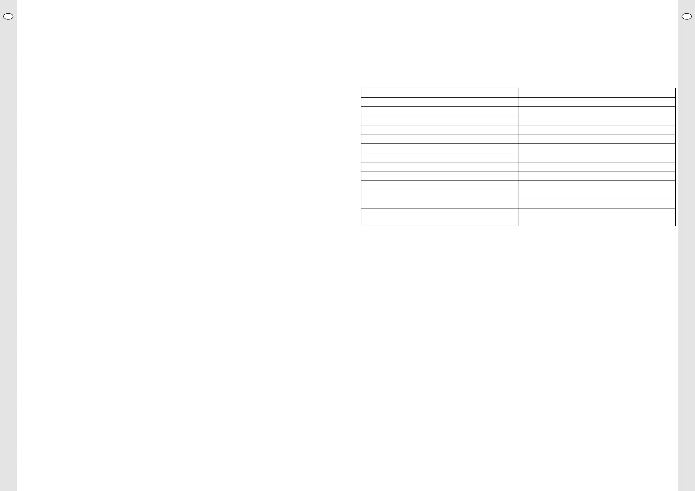
10. Technical data
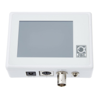
Display Touch 2,8“
pH measuring range pH 3�00 – 9�00� All values outside this range appear as 2�99 or 9�01�
Setting range for pH set point 5,00 – 9,00
Display / pH measurement accuracy 0,01 pH / 0,02 pH*
Temperature measurement range 0,1 – 84 °C
Temperature measurement accuracy 0,06 °C
Temperature compensation automatic
Calibration time max� 1�5 minutes per buer solution
CO₂ content as basis of calculations for auto pH curve 22,5 mg/l
Languages DE/EN-UK/FR/NL/IT/DK/ES/PT/RO
Voltage 12 V DC
Control voltage for solenoid valve 12 V DC
Power input max� 0,5 W
Power supply unit Primary: 100 – 240 V AC, 47 – 60 Hz, 0�25 A
Secondary: 12 V DC, 0�3 A, 3�6 W
* depending on age and condition of sensor
UKUK
24 25
 Loading...