7.7 Valve
Open with the following steps:
Settings key > select Valve > press OK > select “auto”, “man open” or “man shut” > press OK.
In this menu item you can select the operation mode of the externally controlled solenoid valve� The options are automatic operation (auto), manual
open (man open) and manual shut (man closed)� For the regulation feature to work, the “auto“ setting (factory setting) needs to be selected� For the
settings “man open “ and “man closed“, the valve stays open or shut until the setting is changed again�
A green symbol for “open“ or a red symbol for “shut“ and “A“ for automatic or “m“ for manual appear on the value overview (chap� 4)�
7.8 Alarm
The device has a versatile alarm function for the pH value and temperature�
Open with the following steps:
Settings key > select Alarm > press OK > use selection key to select alarm type (“alarm o ”, “flashing”, “flashing and tone”) > press OK
> select your chosen limit values for pH and temperature with „plus“ and „minus“ > press OK.
pH alarm:
If the current pH value in the aquarium exceeds the set target value upwards or downwards by more than the value entered, a warning triangle will
flash on the display and the pH value indication will change to red and flash (if “flashing” was selected)� Where “flashing and tone” was selected, an
acoustic signal will sound as well�
The alarm limit can be set as follows: +/- 0�10 to +/- 2�00 pH in steps of 0�05 pH� Factory setting: +/- 1�00 pH
Tip: We recommend setting the alarm value for the pH to +/- 0,50 to check the function of the CO₂ supply� If the device then triggers an alarm, check
your CO₂ system to see if the cylinder is empty or the supply amount has been adjusted etc�
Temperature alarm:
The temperature alarm function enables you to set the upper and lower alarm limits separately� Thus you can freely select the alarm limits relevant
to your aquarium� If one of the limit values is exceeded or not reached, the same occurs as for the pH alarm�
Factory setting: 20 °C < t < 30 °C
The limit values set appear in the status line on the value overview (chap� 4)�
7.9 Brightness
Open with the following steps:
Settings key > select Brightness > press OK > select the desired value using “plus” and “minus” > press OK.
Factory setting: middle level�
7.10 Contrast
Open with the following steps:
Settings key > select Contrast > press OK > select the desired value using “plus” and “minus” > press OK.
Factory setting: middle level�
7.11 Key lock
Open with the following steps:
Settings key > select Key Lock > press OK > confirm with “locked“/”unlocked“ > press OK.
For selection “locked“ > enter the password (4-digit number) > press OK.
After locking the 4-space number field appears when any key is pressed� Enter the 4-digit password and confirm with OK� The keys are now unlo
-
cked again
� In the event that you have forgotten the password, you can unlock the device with the following master password: 7422�
In the value overview (chap� 4) a symbol for keys locked (red padlock locked) and for keys unlocked (green padlock unlocked) appears�
7.12 Software version
Open with the following steps:
Settings key > select software version > press OK
The version of the software currently installed and the serial number of the device are displayed� This information is only required for service purpo
-
ses
�
7.13 Reset function
Open with the following steps:
Settings key > select “Restore all factory” > press O.K.
If you press longer than 1 sec on OK, all individual settings will be deleted and reset to the factory setting. The master password
7442 is retained.
Factory setting after reset:
Language: German
Calibration reminder: 30 days
Auto pH: ON, KH 8 / pH 7�03
Hysteresis: 0�10
Valve: auto
Alarm: pH +/- 1,00; 20 °C < t < 30 °C
Brightness: medium value
Contrast: medium value
Key lock: unlocked
Master password: 7422
8. Miscellaneous
8.1 Calibration
Display during waiting time: Whilst the sensor is in the buer solutions the device measures the sensor voltage delivered and waits until the signal
has stabilised� This takes a maximum of 1�5 minutes per buer solution�
The following appears on the display during the waiting time:
First line: pH value of the required buer solution and voltage in millivolt
Second line: temperature in °C
Third line: progress bar
The far right of the display also shows the current accuracy of the measurement, which is redefined for the sensor used during each calibration�
Example: +/- 0�02 pH� The higher this value is, the worse the condition of the sensor is�
Calibration reminder: the device has an automatic calibration reminder function which gives you a reminder for calibration every 30, 45 or 60
days� The time to the next calibration is displayed in days and hours in the value overview (chap� 4)� The remaining time display also appears on the
top right of the idle screen 5 days before the calibration period expires� Its colour changes to red two days before calibration is due� After the expiry
of the deadline the display flashes and counts the days with a minus sign, to remind you how many days the calibration is overdue for�
If calibration cannot be carried out at that moment, the device continues to measure and control as before� However, the warning signal (flashing)
can only be cancelled by calibration�
The time to the next calibration can only be recorded as long as the device is connected to the power supply� After a longer pause, it is vital that
calibration is carried out before the device is again used to measure and regulate�
Error messages during or after the calibration:
The measuring behaviour of pH sensors changes with age i�e� it begins to deviate from the original setting� Regular re-calibration of the device (com
-
parison with the changed measuring behaviour of the sensors) is vital to obtain reliable results
� As a rule, the more often, the better�
If, at the end of the calibration process, the symbol of the operating instructions and an error message such as DELTAV, OFFSET or similar appear, the
sensor may be defective� Then repeat the calibration�
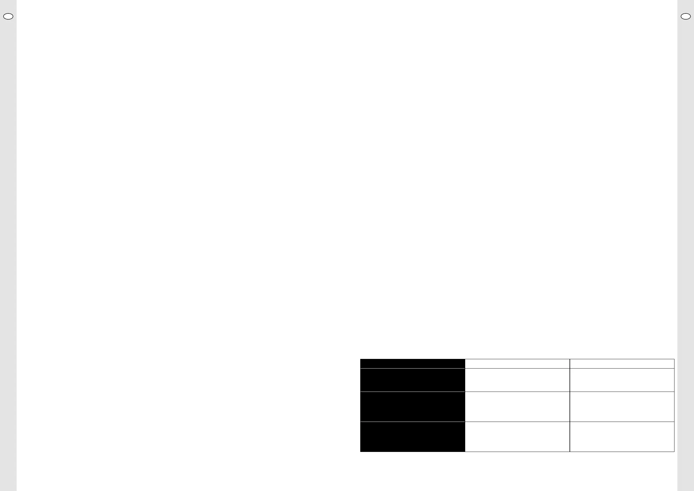
In the event that calibration is unsuccessful a second time, consult the following table:
Error message Cause Solution/Action
DELTAV Voltage dierence per full pH unit is less than
35 mV: sensor too old or accidentally calibrated
twice with same buer solution�
Repeat calibration, check correct buer
solution is used� If unsuccessful, connect new
sensor and calibrate�
OFFSET Sensor voltage at pH 7�00 is outside the range:
sensor too old, cable faulty, no sensor connec-
ted or initially calibrated with buer solution
4
�00 by accident�
Check sensor cable for damage, connect
sensor correctly and repeat calibration (starting
with buer solution 7�00!)� If unsuccessful,
connect new sensor and calibrate�
UNSTAB Unstable sensor voltage: sensor tip soiled,
electrolyte leaked out of sensor or sensor tip
broken o�
Clean sensor tip� If unsuccessful, connect new
sensor and calibrate�
UKUK
22 23
 Loading...