03 - Attachments, Couplings and Load Handling
09 - Lift Arm Quickhitch
06 - Hydraulic Quickhitch
03 - 11 9813/2850-3 03 - 11
8. When the pivot shaft has disengaged from the
hooks, reverse the machine clear. Refer to Figure
18.
Figure 18.
L Pivot shaft
M Hooks
Engage the Attachment
In this procedure, the quickhitch isolator switch is
used to divert the hydraulic power.
1. Align the machine square with the attachment.
2. Lower the lift arm until the pivot shaft is below
the level of the hooks on the attachment. Refer
to Figure 19.
Figure 19.
L Pivot shaft
M Hooks
3. Drive the machine slowly forward, stop when the
pivot shaft just touches the attachment.
4. Engage the park brake and put the transmission
in neutral.
5. Raise the lift arms and engage the pivot shaft into
the hooks. Stop the movement as soon as the
pivot shaft is engaged.
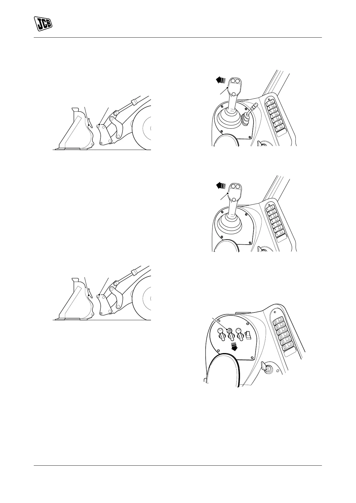
6. Engage the attachment:
6.1. Servo-controls levers: Move the applicable
lever to the left and tilt the Quickhitch fully
back. Refer to Figure 20. Refer to Figure 21.
Figure 20.
H Servo control lever
Figure 21.
J Servo control lever
6.2. Multi-controls levers: Move the lever to the
rear and tilt the Quickhitch fully back. Refer
to Figure 22.
Figure 22.
K Multi control lever (optional)
7. Push and hold the Quickhitch isolator switch.
Refer to Figure 10.
8. Engage the locking pins in the attachment:
8.1. Servo-controls lever with an auxiliary lever:
Pull the lever until the locking pins are
engaged. Refer to Figure 23.