03 - Attachments, Couplings and Load Handling
09 - Lift Arm Quickhitch
06 - Hydraulic Quickhitch
03 - 12 9813/2850-3 03 - 12
Figure 23.
C Auxiliary lever
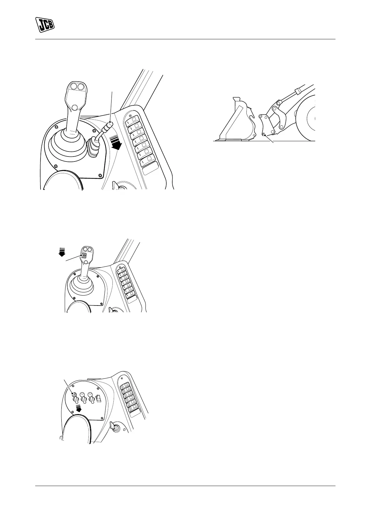
8.2. Servo-controls lever with an auxiliary
switch: Pull the button until the locking pins
are engaged. Refer to Figure 24.
Figure 24.
E Auxiliary roller button
8.3. Multi-controls levers: Pull the lever until the
locking pins are engaged. Refer to Figure
25.
Figure 25.
F Multi control lever (optional)
9. Make sure the red locking pins in the base of the
Quickhitch are fully engaged. Refer to Figure 26.
Figure 26.
B Red locking pins
10. Release the Quickhitch isolator switch. Refer to
Figure 10.
11. If necessary connect the hydraulic hoses.