Optipay® CC JCM Training Overview JCM Training Overview December, 2006
Part No. 960-000153R_ Rev. A © 2006, JCM American, Corporation
22 7
Lecture Notes
Lecture Notes
P
ALM
A66US (C
ONTINUED
)
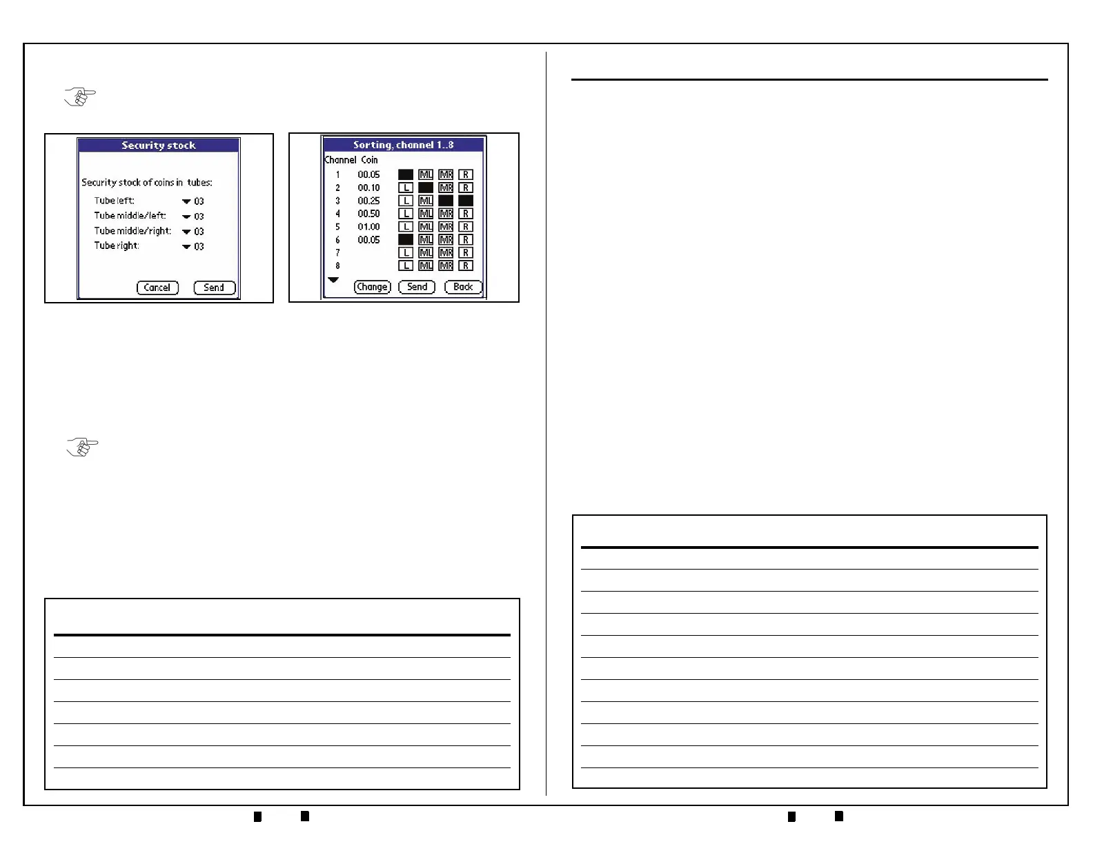
11.To change the tube configuration, select ‘Change’, select a new configuration
from the list of available payout combinations listed and click ‘OK’. The Figure
26 Screen will then reflect the desired setting changes. Click ‘Send’ to transmit
the new settings to the Coin Changer.
12.From the ‘Settings’ Screen, select ‘Recycler’. A Recycler Screen such as that
shown in Figure 27 will appear.
The Recycler Screen indicates that the recycle mode is active. The
amount listed in the
‘Value’ column indicates the bill denomination
currently being recycled. Additional Recycler information is available
via the
‘Diagnostics’ mode screen.
NOTE: Only the first eight (8) coin configuration settings show on the screen. The
small arrow in the bottom left corner of the screen will advance the display beyond
the first eight configurations shown.
Figure 26 Coin Sorting Screen
Figure 25 Security Stock Screen
NOTE: The values represented on this screen are only valid if an optional RC-10
Recycler is present mounted on a DBV-301 Bill Validator and the ‘Recycler active’
Box is checked on this screen!
MECHANICAL LAYOUT & COMPONENTS
V
ALIDATOR
S
ECTION
C
OMPONENTS
• Coin Insertion Funnel — coin entrance and cassette filling
•
Coin Return Switch — coin reject / clear coin jams
•
RJ-45 Connector — for Palm PDA interfacing
•
Validator Unit Locking Tabs — white tab unlocks validator
•
Fly Deck Access Locking Tab — open to clear coin jams
•
Acceptance Gate — accepts/rejects coins; access to sorting gates; flexible lever
provides "stringed coin" protection
•
LED Indicators — provide diagnostic indications of A-66 status
•
Keypad — allows for manual coin payout and pre-load functions
•
Product Label — Part #, coin configuration, operating voltage, etc.
•
40-pin Ribbon Cable — rear of unit, connects to interface board
•
DIP Switch Block — 10-position DIP switch allows for setting coin inhibits and
control functions.
– Default setting is Switches 1 through 8 set to OFF = respective coin channels
enabled
– If Switches 1 through 8 are set to ON the respective coin channels are inhibited
– Switch 9 ON allows all bills to pay out of the RC-10 Recycler Option when
attached to the DBV-301
– Switch 10 ON = MDB Level 3 A-66 operation.
– Switch 10 OFF = MDB Level 2 A-66 operation.