Optipay® CC JCM Training Overview JCM Training Overview December, 2006
Part No. 960-000153R_ Rev. A © 2006, JCM American, Corporation
20 9
Lecture NotesLecture Notes
P
ALM
A66US (C
ONTINUED
)
No correction of tube counters: disables the automatic coin
changer coin tube sensors.
"Tube Empty" function for Bills: disables acceptance of high value
bills when the coin changer is empty or lacks sufficient change for
proper operation.
5. From the ’Settings’ menu screen, click on the ‘Inhibit Mask’ Screen Button.
The screen shown in Figure 21 will appear. Selecting boxes on this page allows
for disabling the respective coin or token channel. If a box is unchecked, the
respective channel is enabled.
6. From the ’Settings’ Screen, select ‘Coin Settings’. Four (4) Sub-menus (i.e.,
Float Level, Filling level limitation, Security stock, and Coin Sorting) will appear
as shown in Figure 22.
7. On the ‘Coin Settings’ Screen, select ‘Float Level’. The screen depicted in
Figure 23 will appear. Set the desired Float Level for each coin tube by using the
respective up and down arrows . The Box allows the float values
to be incremented by one (1) or ten units (10) at a time.
Figure 22 Coin Settings Screen
a
Figure 21 Inhibit Coin Channels
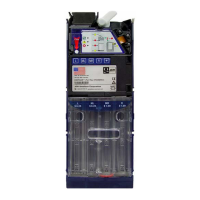
SENSORS & COIN VALIDATION
S
ENSORS
• The coin path in the Validator contains various optical, inductive, and magnetic
sensors used for coin validation and acceptance
• An optical sensor located just below the Acceptor Gate in the Validator Unit
functions as a 'coin accepted' sensor
• An array of optical sensors in the Coin Tube Section are used to keep track of the
current coin levels in each tube (i.e., Empty, 50%, 75%, 100%)
• An optical sensor located on each of the Payout Motors is used to indicate a 'payout
complete' operation. Should a payout error occur, the unit will attempt to clear the
problem and retry three (3) times before timing out.
• An optical sensor is located in the Cash Box Channel. The coin channel itself is
made of opaque plastic allowing the user to visually inspect the specific coin
channel for jams or edge standing coins.
C
OIN
V
ALIDATION
• An inserted coin falls into the Validator section via the funnel where it rides down
the Fly Deck towards the Acceptance Gate.
• It then passes by and through optical, magnetic, and inductive sensors which
operate at various frequencies.
• The sensors measure the various properties of the coin such as diameter, mass,
density, weight, hardness, embossing, alloy type, rim size, and (if applicable)
bi-color attributes like ring material and core laminate material.
The resulting electrical measurements are unique to each coin. Upper and lower
limits are established for the measured values which are stored in memory as
'acceptance band' information.
• As long as a coin measures within the 'acceptance band' window, it is considered
'valid', the 'acceptance gate' opens, and the coin is passed to the coin sorting gates
where it is then sorted either to the correct coin tube or to the cash box, depending
on whether the respective coin tube is full or how the Coin Changer has been
programmed.
• If a coin measures outside of the 'acceptance band' limits, the coin is considered
invalid, is rejected, and exits the Coin Changer via the Coin Return Slot.