EasyManua.ls Logo

Jeep UNIVERSAL CJ-2A - Page 39

Jeep UNIVERSAL CJ-2A
281 pages
Print Icon
To Next Page IconTo Next Page
To Previous Page IconTo Previous Page
Loading...
D
L4-134
ENGINE
connecting
rod
from
which
it
was
removed,
and
in
the
same
position.
After
wiping
and
carefully
in-
specting
the
bearing
bore
in
the
connecting
rod,
install
the
proper
bearing.
Never
file
either
the
bearing
cap
or
the
bearing
to
compensate
for
too
much
clearance.
Do
not
use
shims
under
a
bearing
cap
or
behind
a
bearing
shell.
Do
not
run
a
new
bearing
half
with
a
worn
half.
The
desired
running
fit
(difference
betweea
the
diameter
of
the
crankpin
and
the
inside
diameter
of
the
fitted
bearing)
for a
connecting
rod
bearing
is
.001"
to
.0019"
[0,025 a 0,048
mm.].
With
a
dimension
in
excess
of
this
standard
running
fit, a
satisfactory
bearing
replacement
cannot
be
made
and
it
will
be
necessary
to
regrind
the
crankshaft.
Install
the
bearing
lower
half
and
the
connecting
rod
cap
and
draw
the
cap
bolt
nuts
down
equally
and
only
slightly
tight.
Move
the
connecting
rod
endwise,
one
way
or
the
other,
on
the
crankshaft
to
be
sure
the
bearing
is
not
tight.
Pull
the
nuts
tighter,
first
one
then
the
other,
a
little
at
a
time,
and
keep
trying
the
fit
of
the
rod
on
the
crankshaft
by
hand
until
the
recommended
torque
of
35
to
45
lb-ft.
[4,8 a 6,2 kg-m.] is
reached.
If
the
bearings
are
of
the
correct
size,
and
have
been
properly
lubricated
with
light
engine
oil
before
in-
stallation,
the
connecting
rod
should
be
easy
to
slide
back
and
forth
parallel
to
the
crankpin.
If
the
connecting
rod
is
tight
on
the
crankshaft,
a
larger
bearing
is
required.
If
there
is
no
binding
or
tightness,
it
is
still
necessary
to
check
clearance
to
guard
against
too
loose a fit.
The
use
of
"Plasti-
gage"
or
shim
stock
of
the
proper
size
to
measure
.0010"
to
.0019" [0,025 a 0,0483
mm.]
clearance
is
recommended
for
checking
connecting
rod
bearing
clearances.
This
is
the
same
material
recommended
for
checking
crankshaft
main
bearings
and
the
method
of
checking
is
similar.
Refer
to
Par.
E-46
or
E-4
7.
Connecting
rod
bearings
are
fitted
to
the
same
clearance
as
the
main
bearings
but
the
torque
specified
for
connecting
rod
cap
bolts
is
different.
NOTE:
Should
it
be
necessary
to
replace
a
scored
or
burned
No.
1
connecting
rod
bearing,
see
Par.
D-84
regarding
timing
gear
oil
jet.
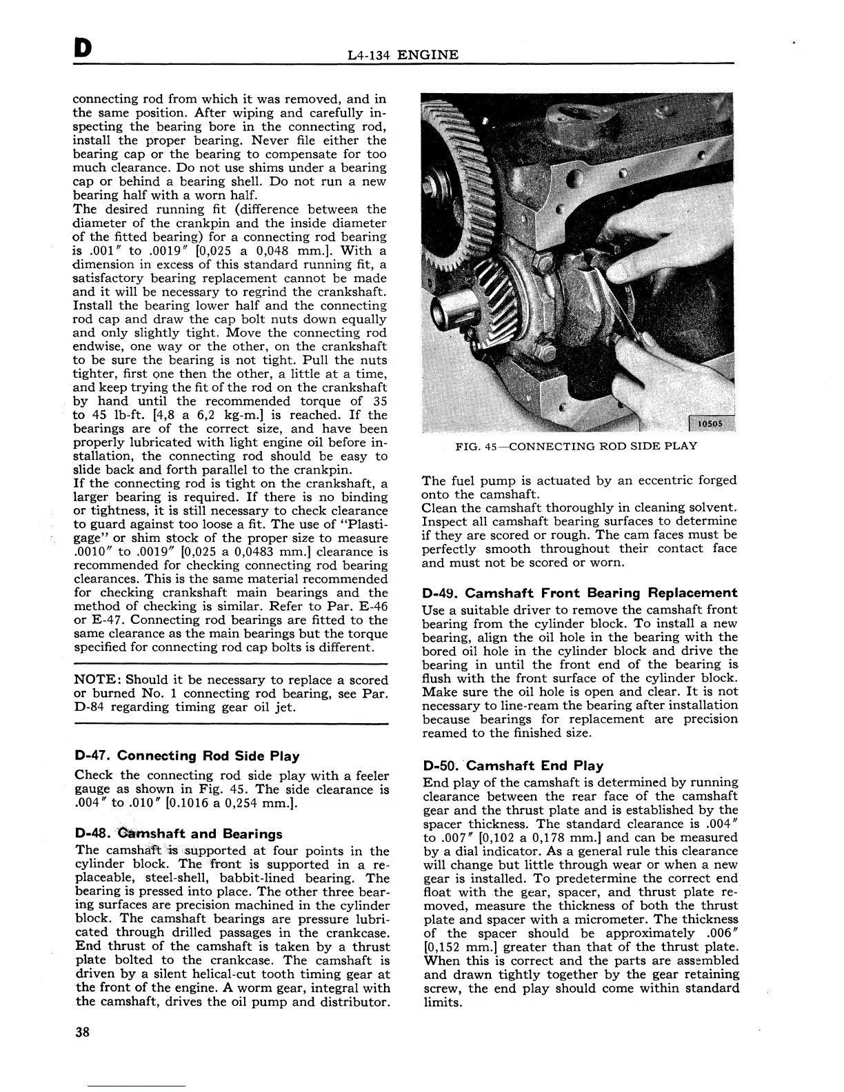
D-47.
Connecting
Rod
Side
Play
Check
the
connecting
rod
side
play
with
a feeler
gauge
as
shown
in
Fig.
45.
The
side
clearance
is
.004"
to
.010"
[0.1016 a 0,254
mm.].
D-48.
o.mshaft
and
Bearings
The
camshaft
is
supported
at
four
points
in
the
cylinder
block.
The
front
is
supported
in
a re-
placeable,
steel-shell,
babbit-lined
bearing.
The
bearing
is
pressed
into
place.
The
other
three
bear-
ing
surfaces
are
precision
machined
in
the
cylinder
block.
The
camshaft
bearings
are
pressure
lubri-
cated
through
drilled
passages
in
the
crankcase.
End
thrust
of
the
camshaft
is
taken
by
a
thrust
plate
bolted
to
the
crankcase.
The
camshaft
is
driven
by
a
silent
helical-cut
tooth
timing
gear
at
the
front
of
the
engine.
A
worm
gear,
integral
with
the
camshaft,
drives
the
oil
pump
and
distributor.
38
FIG.
45-CONNECTING
ROD
SIDE
PLAY
The
fuel
pump
is
actuated
by
an
eccentric
forged
onto
the
camshaft.
Clean
the
camshaft
thoroughly
in
cleaning
solvent.
Inspect
all
camshaft
bearing
surfaces
to
determine
if
they
are
scored
or
rough.
The
cam
faces
must
be
perfectly
smooth
throughout
their
contact
face
and
must
not
be
scored
or
worn.
D-49.
Camshaft
Front
Bearing
Replacement
Use
a
suitable
driver
to
remove
the
camshaft
front
bearing
from
the
cylinder
block.
To
install
a
new
bearing,
align
the
oil
hole
in
the
bearing
with
the
bored
oil
hole
in
the
cylinder
block
and
drive
the
bearing
in
until
the
front
end
of
the
bearing
is
flush
with
the
front
surface
of
the
cylinder
block.
Make
sure
the
oil
hole
is
open
and
clear.
It
is
not
necessary
to
line-ream
the
bearing
after
installation
because
bearings
for
replacement
are
precision
reamed
to
the
finished
size.
D-50.
·Camshaft
End
Play
End
play
of
the
camshaft
is
determined
by
running
clearance
between
the
rear
face
of
the
camshaft
gear
and
the
thrust
plate
and
is
established
by
the
spacer
thickness.
The
standard
clearance
is
.004"
to
.007"
[0,102 a 0,178
mm.]
and
can
be
measured
by
a
dial
indicator.
As
a
general
rule
this
clearance
will
change
but
little
through
wear
or
when
a
new
gear
is
installed.
To
predetermine
the
correct
end
float
with
the
gear,
spacer,
and
thrust
plate
re-
moved,
measure
the
thickness
of
both
the
thrust
plate
and
spacer
with
a
micrometer.
The
thickness
of
the
spacer
should
be
approximately
.006"
[0,152
mm.]
greater
than
that
of
the
thrust
plate.
When
this
is
correct
and
the
parts
are
assembled
and
drawn
tightly
together
by
the
gear
retaining
screw,
the
end
play
should
come
within
standard
limits.