EasyManua.ls Logo

Jeep UNIVERSAL CJ-2A - Page 40

Jeep UNIVERSAL CJ-2A
281 pages
Print Icon
To Next Page IconTo Next Page
To Previous Page IconTo Previous Page
Loading...
'Jeep'
UNIVERSAL
and
'Jeep'
DISPATCHER
D
D-51.
Timing
Gears
(or
Chain)
and
Cover
The
timing
gears
(or
chain)
are
mounted
at
the
front
of
the
engine.
The
silent
type
chain
used
on
the
earlier
engines
is
nonadjustable.
Lubrication
is
positive
through
drilled
passages
in
the
crank-
shaft
and
sprocket
from
the
front
main
bearing.
Oil
passages
should
be
checked
whenever
the
chain
or
sprockets
are
removed
to
make
sure
they
are
clear.
Later
engines
are
equipped
with
helical
cut
timing
gears;
a
steel
gear
on
the
crankshaft
and
a
pressed
fiber
gear
on
the
camshaft.
The
gears
are
keyed
to
their
respective
shafts.
The
camshaft
driven
gear
is
secured
on
the
front
end
of
the
camshaft
by
means
of
a
capscrew
and
a
plain
washer.
The
crankshaft
drive
gear
is
secured
on
the
front
end
of
the
crankshaft
by
a
nut
threaded
onto
the
front
end
of
the
crankshaft
holding
the
crank-
shaft
pulley,
crankshaft
oil
slinger,
and
the
crank-
shaft
drive
gear
spacer.
The
timing
gears
are
lubricated
through
a
jet
threaded
into
the
crank-
case
directly
above
the
gear
contact
and
oil
sup-
plied
through
a
drilled
passage
from
the
front
main
bearing.
The
timing
gears
are
enclosed
by
the
sealed
timing
cover.
The
oil
seal
in
the
cover
bears
against
the
hub
of
the
crankshaft
pulley.
Timing
gears
are
accessible
for
inspection
or
re-
placement
with
the
engine
installed
in
the
vehicle
after
removing
the
radiator,
belt
drive
pulley,
and
timing
cover.
Should
it
be
necessary
to
replace
the
timing
gears,
attention
must
be
given
to
the
end
float
of
both
the
camshaft
and
crankshaft
and
to
the
running
clearance
(lash)
of
both
gears.
It
is
also
advisable
to
check
both
the
oil
jet
and
oil
passage
to
the
crankshaft
front
bearing
to
be
sure
that
they
are
clear.
D-52.
Inspection
and
Repair
Check
the
general
condition
of
both
gears
and
inspect
for
evidence
of
excessive
wear.
Replace
excessively
worn
or
damaged
gears.
Inspect
the
cover
and
replace
if
bent
or
damaged.
It
is
recom-
mended
that
the
crankshaft
oil
seal
in
the
cover
be
replaced
when
the
cover
is
removed
to
ensure
a
good
seal
around
the
crankshaft.
To
replace
this
seal
with
the
engine
in
the
vehicle
requires
removing
the
radiator
and
water
pump.
D-53.
Valves, Springs,
and
Guides
The
valves
seat
on
top
of
the
cylinder
block
with
the
stems
extending
down
through
replaceable
valve
guides.
The
valves
are
actuated
by
the
cam-
shaft
through
valve
tappets.
The
valve
springs
are
assembled
and
locked
on
the
lower
end
of
the
valve
ste~s.
The
retaining
locks
are
the
spl~t
type,
which
fit m a recess
on
the
valve
stems
and
mto
the
taper
in
the
valve
spring
retainers.
Adjustment
of
valves
is
by
means
of
the
adjusting
screw
threaded
into
the
upper
end
of
the
valve
tappets.
D-54.
Inspection
of
Valves,
Springs,
and
Guides
Clean
the
valves
on
a
wire
wheel,
making
sure
that
all
carbon
is
removed
from
the
top
and
the
under-
side
of
the
heads
and
that
all
gum
and
varnish
deposits
are
removed
from
the
stems.
Polish
the
valve
stems
with
steel
wool
or
crocus
cloth.
Visually
inspect
all
valves
for
warpage,
,
cracks,
or
excessive
burning
and
discard
if
one
of
these
conditions
exists.
Replace
any
worn,
pitted,
or
corroded
valves
that
cannot
be
cleaned
with
a
wire
brush.
Replace
any
valves
when
seats
are
pitted,
burned,
or
corroded
so
badly
that
they
cannot
be
cleaned
up
with
a
light
refacing
on
a
valve
refacing
machine.
Replace
valves
with
marks
of
scoring
or
abrasion
visible
on
the
stem.
Replace
any
valves
with
bent
stems
which
will
be
apparent
when
the
valve
is
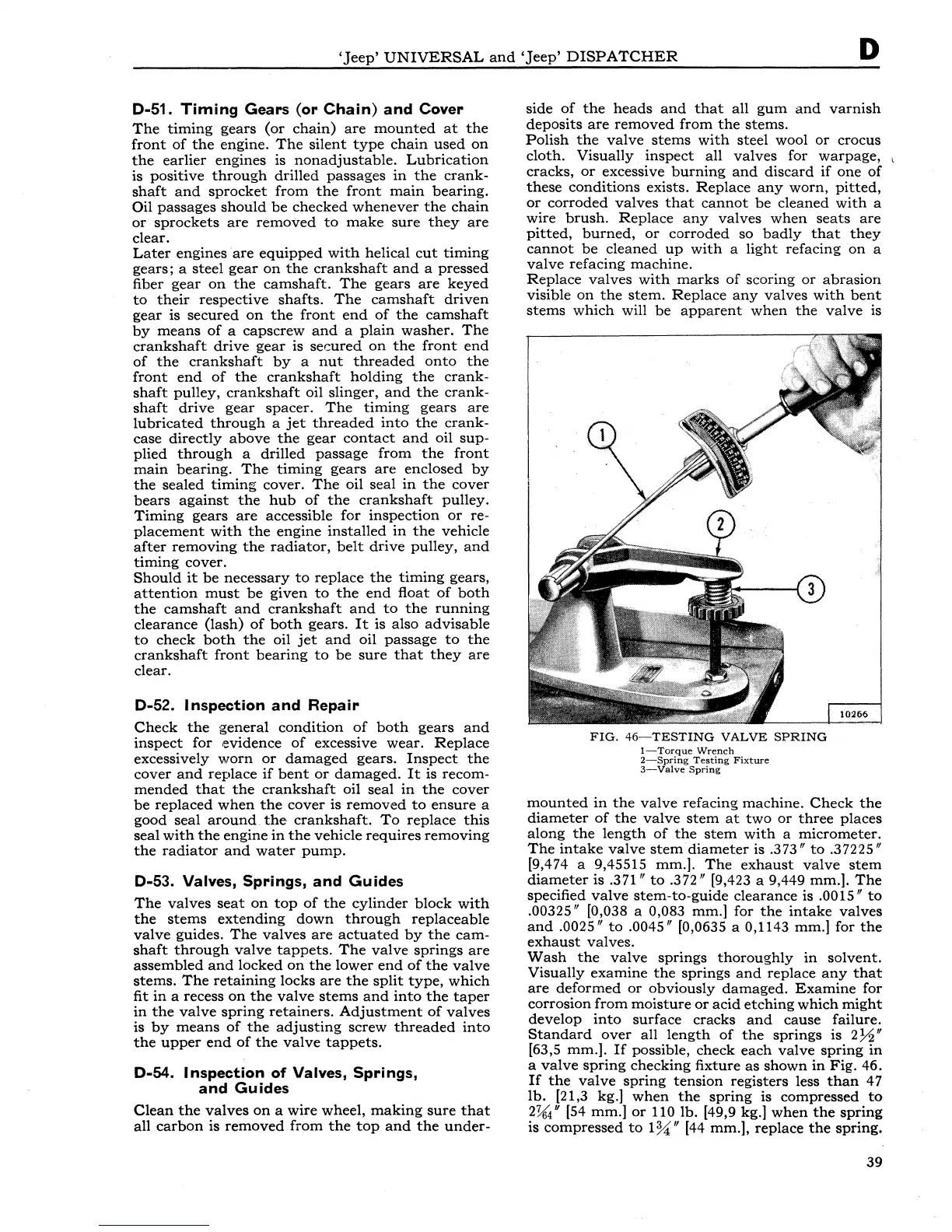
FIG.
46-TESTING
VALVE
SPRING
1-Torque
Wrench
2~Spring
Testing
Fixture
3-Valve
Spring
mounted
in
the
valve
refacing
machine.
Check
the
diameter
of
the
valve
stem
at
two
or
three
places
along
the
length
of
the
stem
with
a
micrometer.
The
intake
valve
stem
diameter
is .373
11
to
.37225
11
[9,474 a 9,45515
mm.].
The
exhaust
valve
stem
diameter
is .371
11
to
.372
11
[9,423 a 9,449
mm.].
The
specified
valve
stem-to-guide
clearance
is .0015
11
to
.00325
11
[0,038 a 0,083
mm.]
for
the
intake
valves
and
.0025
11
to
.0045
11
[0,0635 a 0,1143
mm.]
for
the
exhaust
valves.
Wash
the
valve
springs
thoroughly
in
solvent.
Visually
examine
the
springs
and
replace
any
that
are
deformed
or
obviously
damaged.
Examine
for
corrosion
from
moisture
or
acid
etching
which
might
develop
into
surface
cracks
and
cause
failure.
Standard
over
all
length
of
the
springs
is 2
_Y2
11
[63,5
mm.].
If
possible,
check
each
valve
spring
in
a
valve
spring
checking
fixture
as
shown
in
Fig.
46.
If
the
valve
spring
tension
registers
less
than
47
lb.
[21,3 kg.]
when
the
spring
is
compressed
to
2?£4"
[54
mm.]
or
110
lb.
[49,9 kg.]
when
the
spring
is
compressed
to
1~
11
[44
mm.],
replace
the
spring.
39