Set up of MODE (Operating)
Important! In case of changing this value, the servo amplifier
must be in state POWER OFF (>PQ)..
Inc. per pulse, pulse/direction control
Synchronous ratio for electronic gear
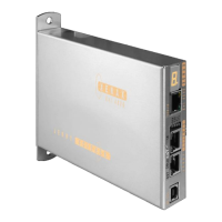
Set CI (query), CANopen Node ID, Powerlink Node ID, Remote
ID in Master/Slave Configuration
Card Identifier of Gantry Slave
Identification string max 16 characters free for user
Max. motor current nominal [x10mA]
Max. motor current peak [x10mA]
Pole-pair number of motor
Number of encoder increments per revolution
Direction of phase control (u,v,w or v,u,w)
Detection of phase control sequence.
By rotating the motor clockwise, 0 or 1 appears. Parameter can
be used to enter the phase control (PHD).
If “?” appears, the Dip-switch is set to linear
in the XENAX® servo controller or the hall wiring is wrong.
Phase Direction Detection
Correction of the electrical angle at new adjustment of coils to
magnets.
Force constant of the motor for LINAX®/ELAX® in [mN/A],
torque constant for rotary motors in [µNm/A]
Resistance phase to phase of the motor in [mΩ]
Phase to Phase Resistance
Inductance phase to phase of the motor in [µH]
Phase to Phase Inductance
Gear ration of rotary Jenny Science motors (ROTAX)
9.6.4 Controller Settings
Payload “PAYLOAD” [g] or
moment of inertia „INERTIA“ [x10
-9
kgm
2
]
Bandwidth position controller “GAIN POS”
Bandwidth current controller “GAIN CUR”
 Loading...