Optional
Equipment
•
Steering
Wheel Control
(SWC)-
The
VX3010
is
SWC
ready for
vehicles
equipped
with
the option.
See
wiring diagram for
installation details.
For
SWC
programming details,
please
see
the operation
manual.
•
Rear
Camera-
The
VX301
0
is
Rear
Camera ready for
vehicles
equipped with the option.
See
wiring diagram
fo
r
installation
details.
Disconnect
the
Battery
•
To
prevent a short circuit, be sure
to
turn
off
the
ignition and remove
the
negative(-) battery cable prior
to
installation.
NOTE:
If
the VX30
10
is
to
be
installed in a car equipped with
an
on-board
drive
or
navigation
computer,
do
not
disconnect the
battery
cable.
If
the cable
is
disconnected, the computer
memory
may
be lost. Under these conditions, use
extra
caution
during installation
to
avoid
causing a short circuit.
Replacing the
Fuse
• When replacing
the
vehicles
Radio fuse always use the proper rated replacement fuse. Using a fuse
with
an
improper rating
could damage the
unit
and cause a fire.
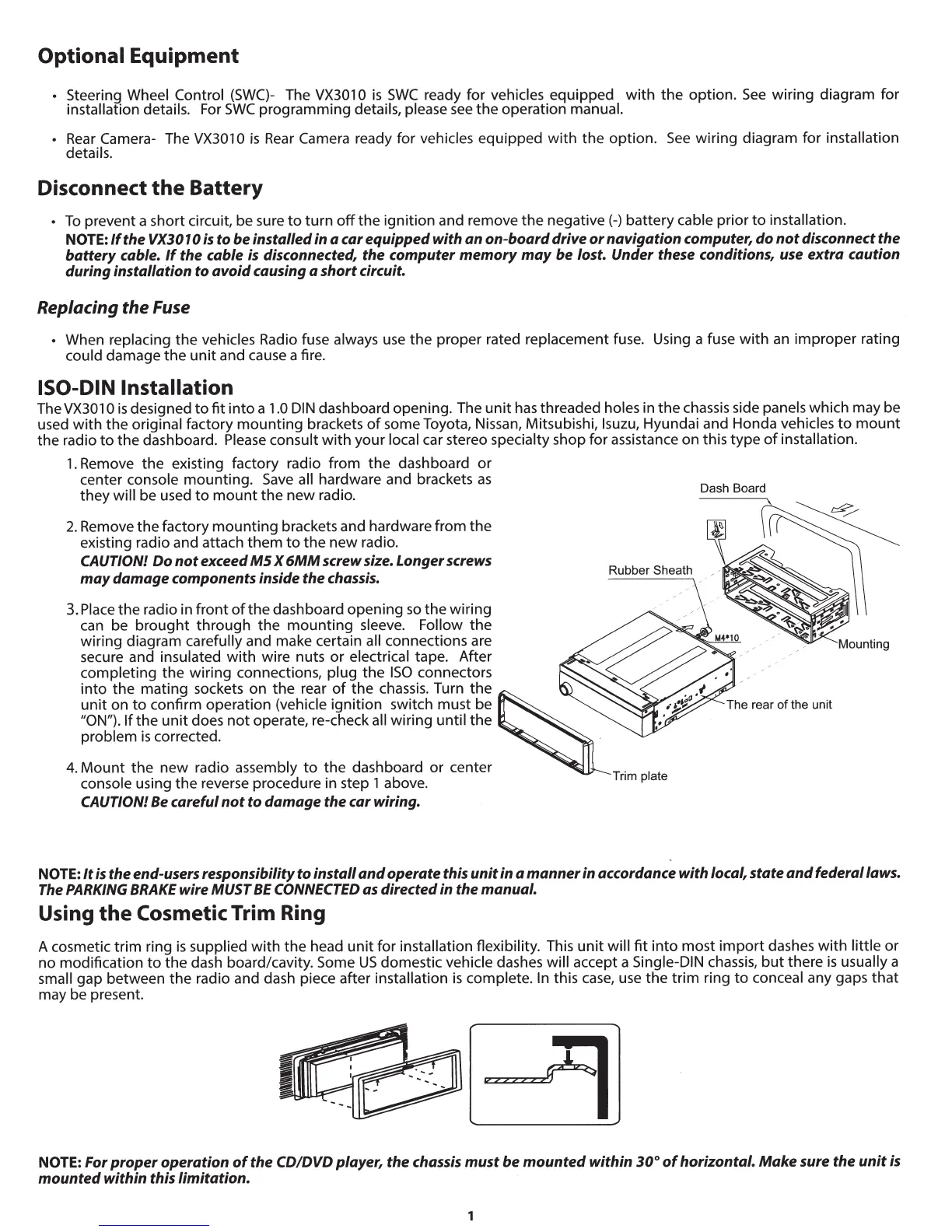
ISO-DIN Installation
The
VX301
0
is
designed
to
fit
into
a
1.0
DIN
dashboard opening. The
unit
has threaded holes in the chassis side panels which may be
used wi
th
the original factory mounting brackets
of
some Toyota, Nissan, Mitsubishi,
lsuzu,
Hyundai and Honda
vehicles
to
mount
the radio
to
the dashboard.
Please
consult
with
your
local
car stereo specialty shop for assistance on this
type
of
installation.
1.
Remove
the
existing factory radio from
the
dashboard
or
center console mounting.
Save
all
hardware and brackets
as
they will be used
to
mount
the
new
radio.
2.
Remove
the
factory
mounting
brackets and hardware from
the
existing radio and attach
them
to
the
new radio.
CAUTION!
Do
not
exceed
M5
X
6MM
screw size. Longer screws
may
damage
components inside the chassis.
3.
Place
the radio in front
of
the dashboard opening
so
the wiring
can be
brought
through the mounting sleeve.
Follow
the
wiring diagram
carefully
and ma
ke
certain all
connections are
secure and insulated
with
wire nuts or electrical tape. After
completing
the
wiring connections,
plug
th
e
ISO
connectors
into the mating sockets on
the
rear
of
the chassis. Turn
the
unit
on
to
confirm operation (vehicle
ignition switch must be
"
ON")
.
If
the
unit
does
not
operate, re-check all
wiring until
the
problem
is
corrected.
4.
Mount
the
new
radio assembly
to
the dashboard
or
center
console using the reverse procedure in step
1 above.
CAUTION!
Be
careful
not to
damage
the car wiring.
NOTE:
It
is
the
end
-users responsibility
to install
and
operate
this
unit
in a
manner
in accordance with local, state
and
federal laws.
The PARKING BRAKE wire MUST
BE
CONNECTED as directed in
the
manual.
Using
the
Cosmetic
Trim Ring
A cosme
ti
c trim ring
is
supplied
with
the
h
ea
d
unit
for
installation flexibility. This
unit
will
fit
into
mo
st
import
dashes
with
littl
e
or
no modification
to
the
dash board/cavity. Some
US
domestic
vehicle
dashes
will
accept a
Single-DIN
chassis,
but
there
is
usually
a
small
gap between the radio and dash piece after installation
is
complete.
In this
case
,
use
the
trim
ring
to
conceal any gaps
that
may be present.
NOTE:
For
proper
operation
of
the
CD/DVD
player,
the
chassis
must
be
mounted
within
30°
of
horizontal.
Make
sure
the
unit
is
mounted
within this limitation.
1