Do you have a question about the JEOL JSM-35C and is the answer not in the manual?
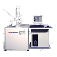
This document provides installation and adjustment instructions for the JSM-35C Scanning Microscope, focusing on the setup and calibration procedures required for optimal performance. The manual is intended for official use, guiding technicians through the initial installation and subsequent electronic adjustments.
The installation process begins with the physical setup of the microscope. It is crucial to ensure adequate working space around the main console, with a minimum distance of 30 inches from surrounding walls or furniture. The Variac, an adjustable transformer, should be installed on a wall at least 7 feet from the column to prevent interference. Additionally, rubber mounts must be placed under the four corners of the column console to provide stability and reduce vibrations.
Wiring is a critical step, requiring careful and neat execution to facilitate future service and maintenance. All cables should be connected correctly, ensuring that modules can be easily pulled out without obstruction. The installation of the anode chamber, main evacuation pipe, and High Voltage (H.V.) cable is detailed, emphasizing the importance of tightening the four screws on the H.V. cable. Before proceeding, the gun chamber must be clean, and the wehnelt assembly, complete with a filament, should be mounted. A final check of the AC 100V in the pump box is necessary, with specific color codes provided for hot (red), black (neutral), and ground wires.
The vacuum sequence is a comprehensive procedure designed to achieve and maintain the necessary vacuum levels for microscope operation. This sequence starts by turning on the "Unattended Operation" switch and the "Key" switch, along with the water supply. A check of the 24V in the pump box is required. The DP indication lamp on the vacuum panel should illuminate for a 20-minute warm-up period. A digital voltmeter (Fluke 2mA range or Data Precision 1mA range) is then attached to the vacuum circuit jack on the left inside of the column console.
The VENT button is depressed to check the multimeter reading, which should indicate approximately 250µA at atmosphere. If the reading is off, R7 in the VG-07L vacuum control circuit needs adjustment. Subsequently, the "Pump-down" button is pressed, and the meter reading should drop to around 25µA within 10-15 minutes with V1 open. The VENT button is then depressed again to confirm the 250µA reading. Another "Pump-Down" cycle is initiated, ensuring that the V1 valve opens and the V3 valve closes at 170µA. If this threshold is not met, R4 needs adjustment (turning it counterclockwise lowers the switch-over point). After the vacuum system is set to DP pumping, the meter reading should fall to 25µA within 10 minutes, though it may take longer initially.
A crucial part of the vacuum sequence is checking the leak rate. After pumping down for 1 hour, the leak rate is measured using a Sanwa multimeter, with a permissible rate of less than 4µA/minute. The procedure for checking the vacuum leak rate involves turning on the DP, RP, V2, and V4 switches on the vacuum circuit panel. The Valve Lock/Auto switch is set to Manual, which stops pumping and closes all remaining valves. The leak rate is then checked every minute for 5 minutes with the digital voltmeter, and the average is calculated. To return to Auto operation, the valve lock switch is set to Auto, and the red warning lamp on the vacuum system should turn off before switching off the DP, RP, V2, and V4 switches.
Further vacuum adjustments include checking if the meter reading is 25µA with the ready lamp on, adjusting R3 if necessary. The H.V. ready lamp should also be on, requiring R5 adjustment if it is not. The column is then vented and pumped down again, ensuring the H.V. ready lamp comes on when the meter is between 27-30µA. If a vacuum gauge is available, R5 is adjusted to turn on the ready lamp when the vacuum is better than 4 x 10⁻⁴ torr. The V4 function is checked by closing the gun isolation manual valve, turning the valve fully clockwise, depressing the VENT button, and verifying that the V4 valve closes and V1 valve opens. If not, the system is pumped down again, and R6 is adjusted. This sequence is repeated until the valve sequence is proper.
The manual also describes an overnight leak rate test, which is essential for obtaining an accurate indication due to outgassing from inside the column. This test involves pumping the column for 2-3 hours, turning off the instrument overnight, and then turning it on again the next morning. The pumping sound of the rotary pump when the V3 valve opens is used to judge the vacuum level; if the column is under high vacuum, the pumping sound should be barely audible or absent.
The potentiometers R3, R7, R4, R6, and R5 are crucial for vacuum control. R5 (Ready Pot) adjusts the H.V. ready point, with a maximum torr of 4 x 10⁻⁴. R6 (Shutter Pot) controls V4 and is used for proper filament exchange sequencing. R4 (High Vac. Pot) establishes the correct V1/V3 switching point. R7 (Meter H Pot) adjusts the meter reading to 250µA at atmosphere, while R3 (Meter L Pot) adjusts the meter reading to 25µA at high vacuum (pirani saturating point).
The electronics adjustments section begins by emphasizing the importance of pushing down the Unattended Operation switch and checking all voltages on the back of the power supply. This switch must be turned on whenever a unit is pulled out or replaced.
The first electronic adjustment is the Scanning Generator Adjustment. The SCAN GENERATOR unit is pulled out, and the primary goal is to synchronize the Slow 2 horizontal speed to 60Hz. The checking procedure involves evacuating the airlock chamber, opening the door, and turning on the PMT switch to detect any light leak. 60Hz noise should appear on the screen as vertical bars at Slow 2. If not, the SYNC. or H. FREQ. potentiometer on the scan-generator is adjusted. If horizontal sweep is not synchronized, black stripes will appear horizontally. The vertical scan speed at Slow 2 is also checked by decreasing the vertical size using Selected Area Y-width and timing the line movement from top to bottom, which should be 25 seconds. If not, V. FREQ. on the Scan Generator unit is adjusted.
Brightness Adjustment for Line, Spot, and WFM is another key electronic adjustment. Before starting, the display unit is pulled out, side panels removed, power extension cable connected, and the Unattended Operation switch turned off. For display brightness, the contrast is set to 12:00 and brightness to 3:00 on the Display unit. SLOW 1 and Wave Form Monitor (WFM) are depressed, and VR3 on DU05C is adjusted for comfortable WFM brightness. The brightness on SEI is adjusted to locate the signal line between the second and third lines from the bottom of WFM. Finally, the Normal button is depressed, and VIEW PIC brightness VR7 is adjusted to make the raster visible but not too bright or too dark.
For recording CRT brightness, the camera is removed. Brightness and contrast are set to 5.00 on CSI. WFM is used to set the SEI signal between the second and third lines (grey). NORMAL and PHOTO are depressed, with exposure setting 6-6. CSI PIC VR8 is adjusted to ensure the raster is not too bright or dark. Then, in SPOT mode, PHOTO is depressed, and CSI brightness is slowly increased until the spot is visible. CSI SPOT VR9 is adjusted to decrease spot brightness, repeating until the spot is visible but not too bright at CSI brightness 10.00. Brightness is then reset to 5.00. In Line mode, PHOTO is depressed, and CSI brightness is gradually increased to 10.00, adjusting CSI LINE VR10 so the line is not too bright. Finally, the camera is replaced.
CSI Focus Adjustment involves setting the F stop aperture to 5.6. A ground-glass focusing plate is placed on the camera, and the beam is focused by adjusting camera length and using an eye-lupe. The spot size is checked with an eye-lupe (at least 15x peak lupe), and CSI static focus potentiometer VR7 (CSI Focus) on the display unit DFC-08C board is adjusted for the smallest possible spot. The camera is removed, the selected area switch is turned ON, and the spot is brought to the top center of the CRT. The spot size is adjusted to be as small as possible using the dynamic focus "Y" potentiometer (VR) on the display unit DFC-08C board. The spot is then brought to the right-hand side center of the CSI CRT, and its size is adjusted using the dynamic focus "X" potentiometer (VR) on the display unit DFC-08C board. Finally, the spot is brought to the center.
CSI Pincushion Adjustment requires removing CSI and turning off the photo blanking switch on the rear panel of the display module. The RAPID 2 button is depressed, magnification is set above 102, and X and Y width are set to maximum. Selected Area Mode and Picture mode are used. A vertical line should appear on CSI; if it's too dim, the brightness potentiometer on the SEI unit is adjusted. The line must be straight; if not, VR6 on the DFC-08C housed in the display unit is adjusted. The line is moved to the bottom of CSI, ensuring it remains straight, adjusting the balance with VR5 if needed. This is repeated at the top of the CRT. The line is then centered, the Photo Blanking switch is turned on, and the Scan Mode switch is set to Picture. After these adjustments, the brightness potentiometer on CSI is set to 5.0, and the camera f-stop to 16. A photograph is taken in Picture Mode (speed 7.7 or 6.6), adjusting the SEI unit's brightness potentiometer for a good photograph with clear corners and numbering characters. Finally, the side panels on the display unit, the Display unit, and the camera are replaced.
Line Scanning Profile (LSP) Image adjustment involves obtaining a mesh image at 200x magnification, switching to LINE mode, and adjusting the Brightness and Contrast potentiometers on the SEI unit to place the LSP image in the middle of the Display screen.
WFM Adjustment refers to SEM-INST-3 of "Quick References for JSM-35C Operations." The brightness and contrast potentiometers on CSI are set to 5.00 as the initial setting. The standard F stop settings are provided: F16 for ASA 400 (Polaroid 52), F11 for ASA 200, F8 for ASA 100, and F5.6 for ASA 50 (Polaroid 55). After completing this adjustment, one picture is taken, and the contrast and brightness settings are recorded. A 6.7 setting is used unless a 50-second exposure is desired by the customer.
Magnification Adjustment is crucial for accurate imaging. It involves checking magnification across all coarse ranges (101, 102, 103, & 104) and at WD15 and WD39. If magnification is consistently off by the same percentage across all coarse ranges, the H amp. or V amp. potentiometer is adjusted. If only one range is off, that specific range is adjusted. Camera focus can also change magnification, so focusing the camera before checking magnification is essential.
The magnification adjustment procedure requires pulling out the magnification unit, connecting the power extension cable, and turning off the Unattended Operation switch. SLOW 1 is used to measure the horizontal distance on the Display. The Working Distance (WD) is set to 15mm, the Coarse magnification button to 102, and a photograph is taken at 200x magnification (100µ is 20mm when photographed). Four meshes on the X and Y axes are measured on both the photograph (Xp & Yp) and the Display (Xd and Yd). The Xo and Yo relations (Xd/Xp and Yd/Yp) are calculated and recorded. If Xo and Yo are not equal (within 4%), the CSI scan width is adjusted.
Further magnification checks involve setting WD to 39mm, coarse magnification to 101, and fine magnification to 50, using a 100U mesh. Four meshes on the X and Y axes on the display (Xdl and Ydl) are measured. Xdl should be 20mm times Xo, and Ydl should be 20mm times Yo. If not, magnification is corrected by adjusting the H,V amp. potentiometer on the top of the magnification unit. The process is repeated with WD set to 15, coarse magnification to 101, and fine magnification to 100, measuring over four grids. If magnification is off, the WD 15 H V amp. potentiometers are adjusted. After all adjustments, a 200x magnification picture with a 100µ mesh is taken. The micron bar size should match the mesh size; if not, VR8 on the PNU-03L board is adjusted.
Auto Focus Adjustment involves pulling out the LENS unit, setting magnification to 600x, WD to 15mm, O.L. to 5.0, and HV to 35KV. The image is focused by adjusting the "OL ADJ" potentiometer on the top of the lens unit. High voltage is then switched to 25KV, and focus is adjusted with the 25KV potentiometer. This is repeated for 15KV and 5KV. Finally, high voltage is turned to 25KV again, WD is changed to 39mm, and focus is adjusted with the "STAGE" potentiometer.
Dynamic Focus Adjustment (Fully Focus) requires setting WD to 15mm, Objective Lens aperture to 240µm (#2), and magnification to 200x. The specimen is tilted to 60°, and the image is focused on the center of the display. The AMPLITUDE knob is set counterclockwise, and the FULLY FOCUS button is depressed. The image should stay in focus; if not, the LEVEL adjustment on the LENS unit is adjusted. The AMPLITUDE knob is then turned to 2 o'clock, and AMP is adjusted to bring the entire image into focus using SLOW 2. A picture is taken with magnification at 200x.
Numbering involves setting numbering characters according to the customer's request. The switches on PNU-02L are adjusted based on a provided table.
The document also includes diagrams of the potentiometers for vacuum control (Figure 3), the DFC-08C board with CSI Static Focus, Display Static Focus, X and Y pincushion, and Vertical/Horizontal Dynamic Focus (Figure 6), the SCAN GENERATOR with scan mode and position controls (Figure 7), the magnification unit with V and H amp potentiometers (Figure 8), the LENS unit with focus adjustments (Figure 9), and the PNU-03L board with character size/interval and position controls (Figure 10). A table for PNU-02L character address settings is also included.
| Type | Scanning Electron Microscope |
|---|---|
| Manufacturer | JEOL |
| Model | JSM-35C |
| Electron Source | Tungsten filament |
| Resolution | 7 nm |
| Stage | Eucentric goniometer stage |
| Specimen Size | Up to 100 mm diameter |
| Detectors | Secondary electron detector |
| Vacuum System | Oil diffusion pump |