EasyManua.ls Logo

JEOL 1010 - User Manual

Default Icon
15 pages
Print Icon
To Next Page IconTo Next Page
Loading...
Version 2017-01-19 for GI use
How to use the Jeol 1010 TEM of GI (Liesbeth own GI version)
1.Load the specimen
Load a grid into the rod holder: USE ONLY THE TOP POSITION (blue arrow),
Specimen selection on 1 (The rear one is only a reserve one- Spec sel 2). Use the
white wing key with a feather tail (red arrow) to insert the slit over the cover: grab the
cover with the red dots oriented in the long axis, turn a quarter and gently open it.
Insert the grid specimen up. Close the cover and remove the wing key. (Check that all
covers are closed before inserting the rod in the goniometer. Be careful to not lose
the wing key and put it back in its hole on the standard.
If not already done, rotate the tilt of the insertion chamber (goniometer) to the zero
position (scale to be read in the scale on the left side) by releasing the lock h (lift it
Question and Answer IconNeed help?

Do you have a question about the JEOL 1010 and is the answer not in the manual?

Summary

Specimen Loading Procedure

Load Grid into Rod Holder

Instructions for placing a grid into the specimen rod holder, including orientation and wing key usage.

Position Insertion Chamber

Setting the tilt of the insertion chamber to the zero position and securing the lock.

Insert Rod into Goniometer

Aligning the grid holder pin with the goniometer slot and inserting the rod.

Specimen Viewing and Image Acquisition

Initial Setup and Software Operation

Turning on HT/FIL, checking readiness, and opening ITEM software for image acquisition.

Magnification, Focusing, and Navigation

Adjusting magnification, focusing, using XY controls, and applying wobbler for image stability.

Exposure Control and Image Saving

Setting exposure levels, adjusting histogram, and saving images with scale bars.

TEM Alignment and Diaphragm Adjustment

Condenser Diaphragm Settings

Procedure for adjusting upper and lower condenser diaphragms for beam control.

Filament Adjustment and Visibility

Making the filament visible and adjusting it to remove pin shadow.

Fresnel Fringes and Astigmatism Correction

Adjusting Fresnel fringes on a test grid and correcting astigmatism.

Alignment for Assistants (Holy Grid)

Detailed alignment steps for assistants using a holy grid for beam centering.

Troubleshooting and Session Conclusion

Common Troubleshooting Steps

Resolving issues like lost camera vision and vacuum loss during rod insertion.

Session Finalization and Unloading

Concluding the session by switching off components and safely unloading the specimen holder.

Pumping System and Screen Issues

Monitoring pumping system status and resolving bright spot issues on the screen.

Overview

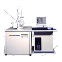
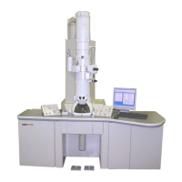
This document outlines the operational procedures and maintenance considerations for the JEOL 1010 Transmission Electron Microscope (TEM), specifically tailored for GI use. The TEM is a sophisticated instrument designed for high-resolution imaging of specimens by transmitting a beam of electrons through them.

Function Description

The JEOL 1010 TEM functions by generating an electron beam, which is then focused and directed through a thin specimen. The electrons interact with the specimen, and the transmitted electrons are then magnified and projected onto a phosphorescent screen, creating a visible image. Alternatively, a digital camera (CCD) can capture and archive the images. The TEM allows for detailed observation of the internal structure of materials at a very high magnification, providing insights into their morphology, composition, and crystallographic information. Key functions include specimen loading, viewing, image acquisition, and various alignment procedures to optimize image quality.

Usage Features

Specimen Loading:

  • Specimens are loaded onto a grid, which is then placed into a rod holder.
  • Crucial: Use only the top position (indicated by a blue arrow) for the grid. Specimen selection on "1" is the primary position; "2" is a reserve.
  • A white "wing key" with a feather tail (red arrow) is used to insert the slit over the cover. The cover, marked with red dots, should be oriented in the long axis, turned a quarter, and gently opened.
  • The grid specimen is inserted facing upwards. After insertion, the cover is closed, and the wing key is removed and returned to its designated hole.
  • Before inserting the rod into the goniometer, ensure all covers are closed to prevent vacuum loss.
  • The tilt of the insertion chamber (goniometer) must be rotated to the zero position. This is achieved by releasing a lock (labeled "h") by lifting it slightly, and then closing it (pushing "h" down to a vertical position) when ready.
  • The pin of the grid holder must be aligned with the slot in the goniometer. The grid rod is gently pressed straight into the opening.
  • To ensure proper contact, press the rod cylinder (metal color) with a flat hand palm until a green light illuminates.
  • Wait for the green light to extinguish.
  • Without delay, slowly turn the rod one quarter clockwise and guide it into the column until fully inserted. Do not release the holder until the rod is completely in place.

Viewing Specimen and Acquiring Images:

  • Power On: Press the HT knob (1) under the plastic cover; it should light up. Verify the green "ready" light is on and the beam current (3) rises to 040. Press the FIL knob (2); its green "ready" light should also come on, and the current (3) should rise from 40 to about 60μA.
  • Software: Open the ITEM software from the desktop icon.
  • Intelligent Exposure: Press the "Intelligent exposure" button (pink cross).
  • Magnification: For imaging below 800x, press the "LOW MAG" knob in the Magnification Selector panel. The lower diaphragm handle "f" should be switched to the right. For magnifications above 800x, use "MAG 1" and turn diaphragm "f" to the left.
  • Magnification Factor: Use switch (4) to modify the magnification factor. "MAG 2" is for pre-set magnifications. Using standard magnification steps is recommended for image comparison.
  • Navigation: Use knobs (14) and (15) for XY navigation.
  • Brightness: Spread the electron bundle evenly over the field of view using the brightness knob (12).
  • Centering: Use the Shift knobs (10) and (13) on the right and left panels to center the bundle. Making the bundle small helps in judging the center. When dimming brightness, it's best to use the clockwise turning range of the knob.
  • Focusing: Use knobs (5), (6), and (7). Option (5) (16x) provides very coarse focusing and can be used with both the macro (6 coarse) and micrometer (7 fine) knobs. Without 16x, finer tuning is possible. There are four grades of focusing.
  • Wobbler Function: To improve focus, use the wobbler function (x and y, 8 and 9) and adjust until the image on the screen is stable.
  • Image Acquisition: Press the right camera icon for intelligent exposure. The system automatically records gray levels displayed on the histogram. Adjust brightness to center and broaden the histogram, ensuring many gray levels are recorded, while keeping exposure time short to minimize vibration bias.
  • Manual Exposure: If automatic balancing is unsuitable (e.g., very dark or bright specimen parts), manual exposure can be applied to a Region of Interest (ROI). This involves clicking the green screen icon within the Intelligent exposure pop-up window and dragging an ROI. Manual minimum/maximum settings and gamma adjustment are also available.
  • Saving Images: Enter the correct magnification (read from the small hardware monitor) and image name in your designated folder (D:>Users> path). Scale bars are automatically added. Images can be uploaded to a server after the session.

Finishing a Session:

  • Return to small magnification (lower diaphragm handle to the right).
  • Take one final picture to discharge the camera chip.
  • Switch off the filament (2).
  • Unloading Specimen: Always ensure the FILAMENT IS OUT. Gently pull the rod to its final stop. Turn it one quarter anti-clockwise. Release the rod by holding one finger against the goniometer to counter the vacuum suction, allowing controlled removal.
  • If you are the last user, switch off the HT (1).
  • Exit the program.
  • Place the grid rod holder on the standard. Release the grid cover with the wing key. Allow the grid to fall onto a clean piece of paper and use tweezers to return it to the grid box. Close the cover and secure the wing key.

Alignment Procedures (for assistants only):

  • Holy Grid Insertion: Insert a holy grid as described for specimen loading.
  • Initial Settings: Go to Mag1 (lower diaphragm handle 'f' to the left), set magnification to LOW (switch 4 to the left), 800x. Spread the bundle with the brightness knob.
  • Step A: Switch handle 'f' of the lower diaphragm to the right. Close the beam as much as possible and use the shift knobs (left and right) to center the spot on the small dot on the phosphor plate. Spread the bundle with the brightness knob. Center the spread bundle using the lateral and front knobs of the upper diaphragm (handle directed to the left). Repeat these steps as necessary.
  • Diffraction: Switch back the lower handle 'f' to the left. Press the Diff (diffraction) button on the right panel. Make a bright narrow pin spot and center the surrounding halo using the left and right DEF knobs.
  • COND STIG: Spread the bundle and press Mag1 again (Dif goes out). Click on COND STIG in the left panel. Turn the brightness knob left and right. The bundle should remain round; if elliptical, correct with the Def knobs left and right. Press COND STIG again when ready.
  • Astigmatism Correction (High Magnification): Using the holy grid, find a small hole at high magnification (e.g., 100000x). Apply underfocus to make Fresnel rings appear (lateral shadows instead of well-centered rings). Adjust the center with screws xx and yy. Apply just enough defocus so the rim appears slightly in one axis.
  • OBJ STIG: Switch on OBJ STIG (objective stigmator on the left panel). Use DEF left and right for big steps, use the 16x knob on the left panel (between Brightness and Def). Iterate until the rim is central to the hole. When ready, switch OBJ STIG off, focus, and check with the wobbler for stability.

Maintenance Features

Filament Saturation Check:

  • Start High Tension (HT) and filament (Fil).
  • Remove upper and lower condenser diaphragms by switching level 'c' to the right.
  • Adjust brightness (12) up and down, adjusting over and underfocus. A well-centered filament should produce centered beam position swings. Adjust centering with screws Shift (10) and Shift (13).
  • If the filament (hairpin) becomes visible, very slightly adjust the filament knob (under the brownish cover on the right panel) clockwise until the pin shadow disappears.
  • Close the brownish lid. Spread the beam with brightness. Reinsert the upper diaphragm 'c' and the lower diaphragm.

Upper/Condenser Diaphragm Adjustment:

  • Switch HT and Fil on. Go to LOW MAG and spread the beam.
  • The upper diaphragm should be directed to the left (standard operating position, except for filament adjustment).
  • Note: Users should never touch this diaphragm; only trained backup personnel.
  • Find one edge of the diaphragm by gently turning screw 'a' clockwise. Turn screw 'a' counter-clockwise, counting turns, until the other edge is found to determine the center.
  • Use screw 'b' (insert completely until stop, carefully) to prevent the diaphragm from falling into the column.

Fresnel Fringes Adjustment:

  • Insert a carbon test grid (consult Geert-Jan). Put HT and Fil on.
  • Go to low magnification to find a nice piece of membrane.
  • Use low mag with level 'f' directed to the left.
  • Check astigmatism by defocusing slightly with knob (7).
  • If Fresnel fringes appear as lateral shadows in the holes of the carbon grid (instead of well-centered rings), adjust the center with screws xx and yy.

Troubleshooting (Bugs):

  • Camera/Eye Vision Switch Lost: Check that "2x enabled" is chosen in Image > Configure input > macro.
  • Vacuum Lost: If vacuum is lost during rod insertion, switch off with the key under the door (left front wing, below table surface), then switch on again. Vacuum restoration takes about 20 minutes, monitored on the small monitor (page down on the second keyboard to browse menus).
  • Manual Switch Camera Touched: If the manual switch camera has been touched, perform one "acquire round" to reopen the camera.
  • Bright Spot Unmovable: If a very bright, unmovable spot appears in the middle of the screen:
    • Switch off filament and HT.
    • Open the left door under the front side of the table.
    • Switch off Lens power and wait a few seconds.
    • Switch Lens power switch to ON again.
    • Switch HT and FIL on again.

Theoretical Resolution and Aberrations:

  • The TEM's resolution is described by Abbe's equation, modified by DeBroglie's formula. Resolution (r) is inversely proportional to wavelength (I). Increasing accelerating voltage shortens the electron wavelength, thereby increasing resolution.
  • Chromatic Aberration: Occurs when electrons of different energies converge at different focal planes. To correct, increase accelerating voltage, improve vacuum, or use a thinner specimen.
  • Spherical Aberration: Electrons passing through the lens periphery are refracted more than those along the axis, preventing them from reaching a common focal point. An aperture is used to eliminate these peripheral electrons.
  • Astigmatism: A lens field that is not symmetrical in strength. Caused by imperfect polepiece boring, non-homogeneous materials, or dirt. A stigmator applies a correcting field to counteract asymmetry. Stigmators are located in the objective and condenser lenses.

This comprehensive guide ensures proper operation and basic troubleshooting for the JEOL 1010 TEM, facilitating high-quality imaging and analysis.

JEOL 1010 Specifications

General IconGeneral
TypeTransmission Electron Microscope (TEM)
Electron SourceTungsten filament
Accelerating Voltage40, 60, 80, 100 kV
Resolution0.5 nm
Magnification50x - 600, 000x
Specimen Size3 mm diameter
DetectorFluorescent screen, CCD camera
Imaging ModesBright field, Dark field

Related product manuals