8
Assembly
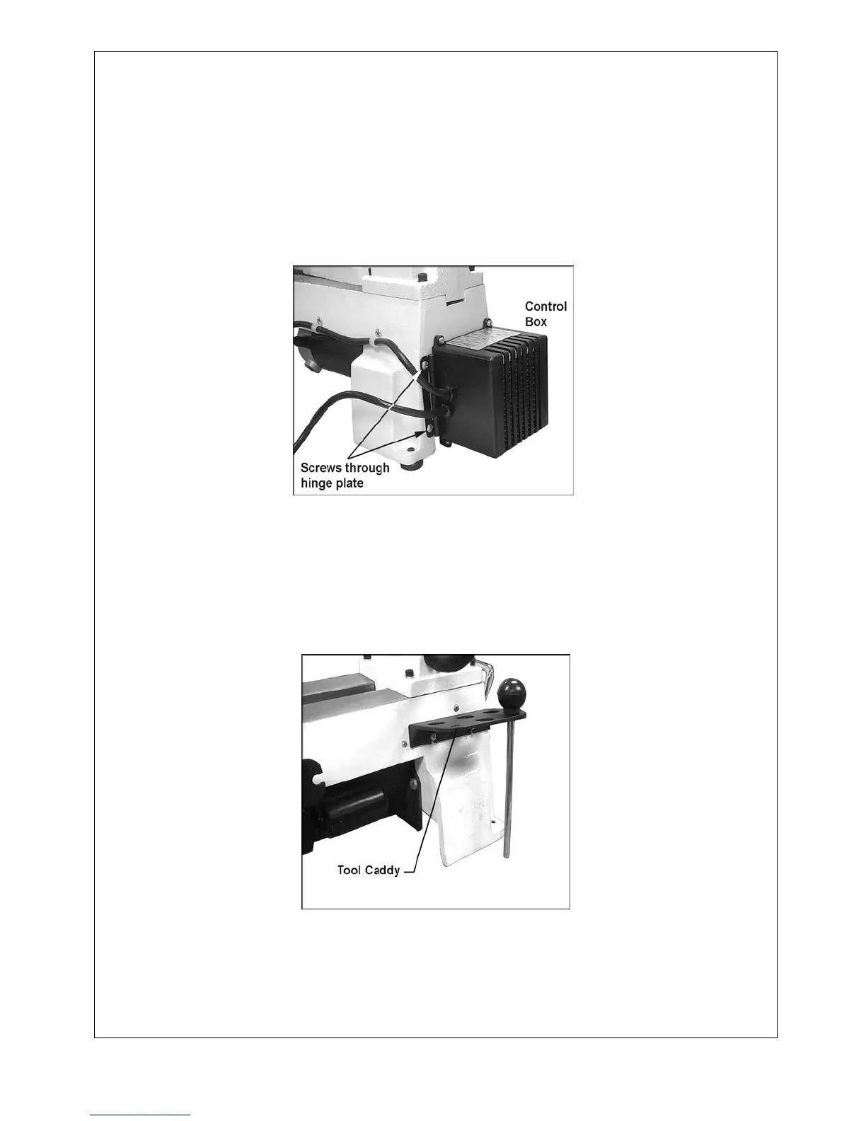
Mount the control box (shown in Figure 1) to the headstock side of the lathe, by inserting the two screws
through the hinge plate and into the threaded holes in the lathe body. If desired, the lathe can be bolted to
a work table or stand by removing the rubber feet and inserting screws through the holes in the base.
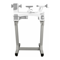
NOTE: The table or stand should have an opening directly beneath the motor to prevent build-up of
shavings around the motor’s fan housing. Stands specifically made for these lathes are available (JML-
1014VSI, Stand Stock #708354) and (JWL-1220VS, Stand Stock #708378).
(Figure1)
The JWL-1220VS requires minor assembly: Install the tool caddy using the two pan head screws, as
shown in Figure 1a. The JWL-1220VS is provided with a lifting handle on each end. These can be pushed
in when not in use.
(Figure 1a)