14
8.4 Fence adjustment
The fence extensions must be
extended to left or right, or removed entirely, when
making bevel cuts, to prevent blade or guard
obstruction. Failure to comply may cause serious
injury.
Failure to extend the fence will not allow enough
space for the blade to pass through. This could
result in serious injury. At extreme miter or bevel
angles the saw blade may also contact the fence
resulting in damage to equipment as well as
personal injury.
IMPORTANT: Make a “dry run” of the cut, including
downward and sliding paths, and resolve any
potential fence obstructions before turning on the
saw.
To adjust fence:
1. Raise lock handle (F, Figure 8-2) to unlock
fence extension.
2. Slide fence extension (K) outward to
accommodate desired bevel angle, or slide it
completely off.
3. Push down lock handle (F) to tighten fence
extension in position.
Note: Secure fence extensions in position closest to
saw blade when transporting the miter saw.
8.4.1 Checking fence squareness
1. Unplug saw from electrical outlet.
2. Loosen four fence locking screws (G, Figure 8
2). Note: Two locking screws to each fence.
3. Lower cutting head and lock in position.
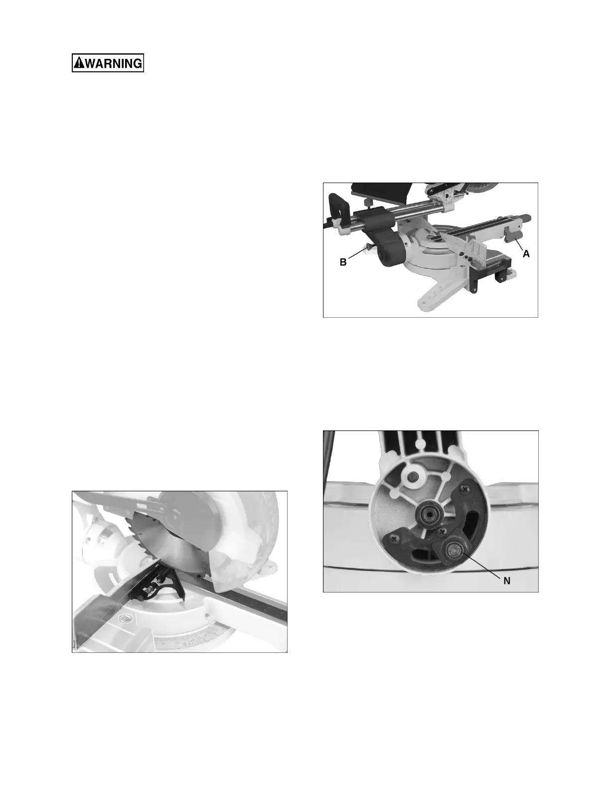
4. Place a combination square against fence and
blade, as shown in Figure 8-3.
Figure 8-3
5. Adjust fence square to blade and tighten the
four fence locking screws (G, Figure 8-2).
6. After fence has been aligned, use a scrap piece
of wood to make a cut at 90º, then check
squareness of the piece. Readjust if necessary.
8.5 Bevel adjustments
8.5.1 90° (zero) bevel stop adjustment
1. Unplug saw from electrical outlet.
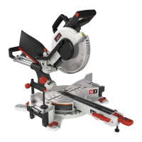
2. Pull up bevel lock handle (A, Figure 8-4) to
unlock tilt mechanism.
3. Pull out on bevel pin (B, Figure 8-4) and tilt
cutting arm to 90° position (0° on bevel scale)
against positive stop.
4. Push down lock handle (A) to secure cutting
head angle.
Figure 8-4
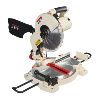
NOTE: If lock handle (A) is disengaged and bevel
pin (B) has been pulled out, but cutting head still
refuses to tilt, the lock nut may have been
overtightened for shipping purposes. Remove three
screws and open rear cover (see Figure 8-5).
Slightly loosen lock nut (N, Figure 8-5) with wrench.
Reinstall rear cover. This adjustment is only if
necessary.
Figure 8-5
5. Place a combination square flat on the table
and against blade, as shown in Figure 8-6.
Note: Position the square flush against main
blade surface, not against a projecting blade
tooth.