13
Cord length Wire gauge (AWG)
0 – 25 ft. 16
25- 50 ft. 14
Table 3
Important: Make certain the receptacle in question
is properly grounded. If you are not sure, have a
registered electrician check the receptacle.
8.0 Adjustments
Note: Your miter saw was adjusted by the
manufacturer. However, during shipment slight
misalignment may have occurred. Check the
following settings and adjust if necessary prior to
using this miter saw.
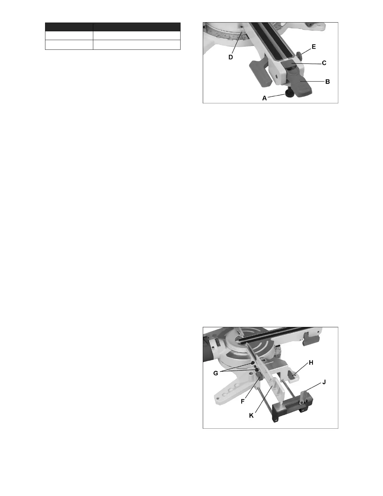
8.1 Support foot
The foot (A, Figure 8-1) can be turned in or out to
adjust its height. It is designed to provided support
for the miter table when locking handle is pushed
down or when cutting head is brought forward for
slide-cutting. The foot should be adjusted to contact
surface of bench or worktable.
8.2 Miter angle setting
The miter scale shows miter angles from 0° to 52°
to the left, and 0° to 60° to the right.
To set miter angle:
1. Lift up on miter lock handle (B, Figure 8-1) to
unlock table.
2. Press and hold release button (C) and use miter
lock handle to push cutting arm until desired
degree aligns with angle indicator (D).
3. Push down miter lock handle (B) to lock the
position.
Note: The release button (C) can be continuously
engaged to bypass the stops. This is convenient
when frequent and quick adjustment of miter angles
is needed.
1. Push down release button (C) and push in pin
(E). Release button is now continuously
engaged.
2. Grasp handle (B) and freely rotate cutting arm.
3. Press release button (C) again to disengage
pin.
Figure 8-1: selecting miter angles
8.2.1 Miter positive stop selection
The miter saw table has preset stops for quick and
accurate positioning at common angle settings of 0°,
15°, 22.5°, 31.6°, and 45° left and right; and 60°
right.
1. Lift up on miter lock handle (B, Figure 8-1) to
unlock table.
2. Press release button (C) and move table with
handle (B). As scale indicator approaches the
desired degree, release the button (C). The
table will engage the next positive stop.
3. Push down miter lock handle (B) to lock the
position.
8.2.2 Miter scale indicator alignment
1. Rotate table to the 0° stop.
2. If indicator (D, Figure 8-1) does not align with
zero on scale, loosen screw and adjust indicator
to 0° mark. Retighten screw.
8.3 Table extensions and work stop
Pull up lock handle (H, Figure 8-2) and slide table
extension outward, as shown. Push down lock
handle to secure position.
Raise workstop (J) for quick positioning of stock
when cutting multiple pieces of equal length.
Figure 8-2