S
Sara HarperAug 14, 2025
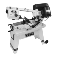
Why is the blade breaking so much on my Jet J-8201?
- CCaitlin WadeAug 14, 2025
Excessive blade breakage in your Jet Saw can stem from several issues. Ensure the material is securely clamped. Incorrect speed or feed settings can cause breakage; consult a Machinist’s Handbook for appropriate settings. Using teeth that are too coarse for the material, incorrect blade tension, saw blade contact with the workpiece before starting, blade rubbing on the wheel flange, misaligned guides, or cracking at the weld can also contribute to this problem. Adjust blade tension, tracking and guides. For cracking at the weld a longer annealing cycle is recommended.