6
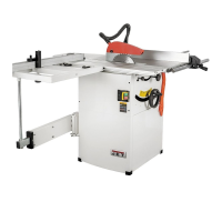
Fig 2
Mounting machine to stand:
Access the machine inside by
removing the front cabinet cover
(bayonet mount, loosen screws and lift
off the cover, Fig 3)
Fig 3
Use lifting straps to lift the machine.
Warning:
The machine is heavy (145 kg)!
Assure the sufficient load capacity
and proper condition of your lifting
devices.
Never step underneath suspended
loads.
Attach the machine to the stand with
the supplied hex socket bolts and
washers.
Mounting telescopic arm:
Place the mounting plate on the inside
of the cabinet and attach the
telescopic arm with the supplied hex
socket bolts (Fig 4)
Fig 4
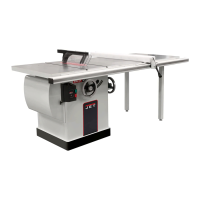
Mounting table extensions
Attach rear extension table (A, Fig 5)
to the machine table with hex head
screws and washers.
Attach right extension table (B) to the
machine table with hex head screws
and washers.
Put table surfaces in level to the main
table.
Use the rip fence profile to check and
the grub screws (C) to adjust.
Fig 5
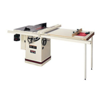
Mounting rip fence support bar
Mount the rip fence support bar (Y, Fig
6) to the front of the saw table and
right table extension.
Fig 6
Mount the scale carrier (W).
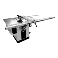
Mounting rip fence
Mount the rip fence to the rip fence
support bar.
Fig 7
The rip fence must be guided parallel
to the table surface. Adjust the round
bar (Y) up-down as needed.
Mounting sliding table:
Loosen the screws and lift the sliding
table end covers
Loosen 2 screws and lift the sliding
table end cover.
Slide the sliding table carefully over
the 4 guide rollers (Fig 8).
 Loading...