8
Assembly
Front
Back
A
G
L
K
Q1
R1
S1
Q3
Q2
R2
S2
R3
S3
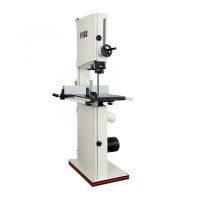
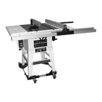
Figure 1
Stand
Referring to Figure 1:
1. Place the band saw (A) on its back as
shown above, either on the floor or
preferably on a workbench.
2. Assemble four legs (G) to the inside of the
base of the bandsaw, securing each leg with
two ea. M8x16 carriage bolts (Q
1
), M8 flat
washers (R
1
) and M8 hex nuts (S
1
). Hand-
tighten only at this time.
3. Attach a long plate (L) to the rear legs as
shown in Figure 1. Secure with 2 ea M8x16
carriage bolts (Q
2
), M8 flat washers (R
2
),
and M8 hex nuts (S
2
). Hand-tighten only at
this time.
4. Attach the remaining long plate to the front
legs in the same manner described above,
hand-tightening only
5. Attach two short plates (K) to the right legs
and left legs in the same manner. Secure
each leg with 2 ea M8x16 carriage bolts
(Q
3
), M8 flat washers (R3), and M8 hex nuts
(S
3
). Hand-tighten only at this time.
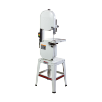
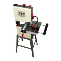
6. Slip rubber feet (Figure 2) onto the ends of
the stand legs.
Figure 2
7. Place the saw and stand upright on a level
surface. Make sure that all four legs are
contacting the surface.
8. Tighten all nuts with a 13mm socket or
wrench.
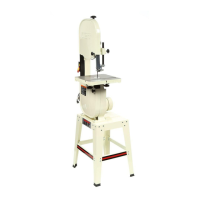
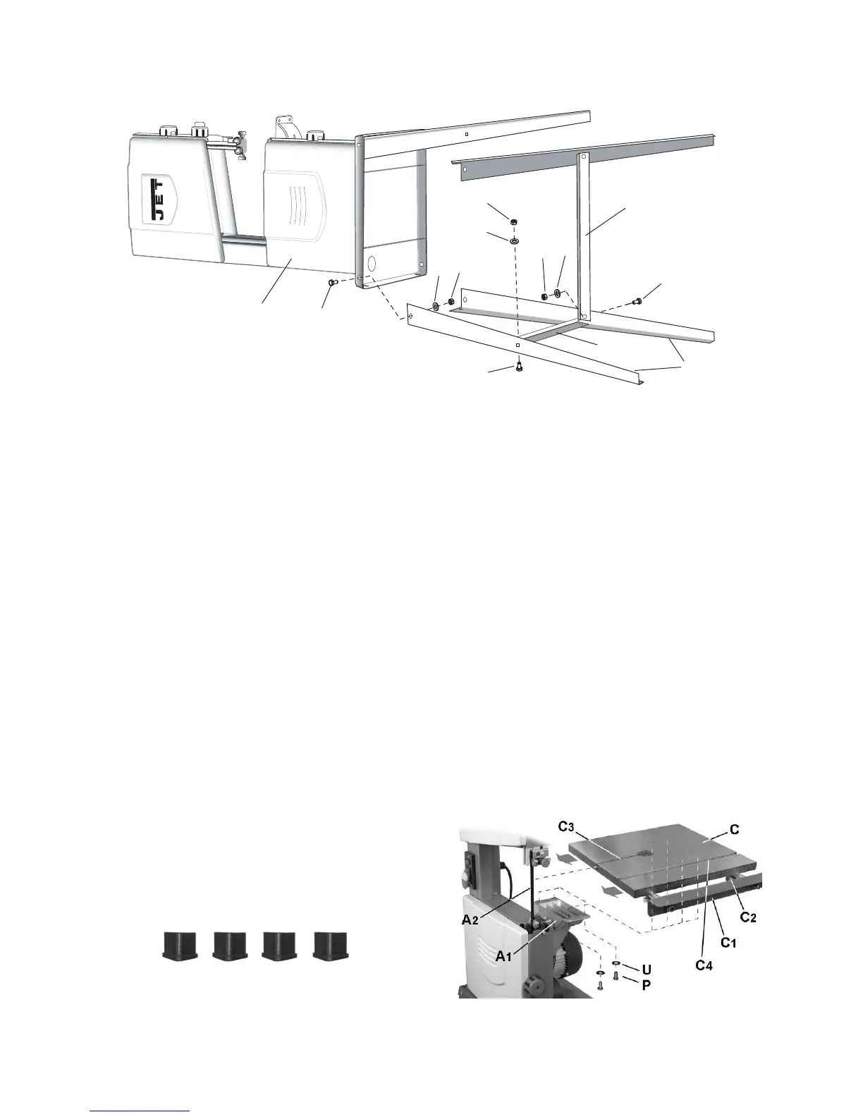
Table Installation
Referring to Figure 3:
1. Loosen lock knob (C
2
) and pull extension
(C
1) out from the table (C).
2. Orient the table (C) as shown, then maneuv-
er to allow the saw blade (A
2
) to pass
through the slot (C
3
) to the center.
3. Line up four threaded mounting holes
underneath the table (C) with the four
mounting through-holes on the trunnion (A
1
).
Important: Adjust table so miter slot (C
4
) is
parallel with saw blade (A
2
).
4. Secure with four each M6x12 hex cap
screws (P) and M6x12 external tooth lock
washers (U).
5. Tighten the screws (P) with a 13mm wrench.
Figure 3
 Loading...