S erial to Ethernet module USR-TCP232-T24 series http://en.usr.cn
Jinan USR IOT Technology Limited Page 14 of 53 tec@usr.cn
2.
2.
2.
2. 3
3
3
3 .2
.2
.2
.2 Hardware
Hardware
Hardware
Hardware Description
Description
Description
Description
2.
2.
2.
2. 3
3
3
3 .21
.21
.21
.21 Pin
Pin
Pin
Pin Description
Description
Description
Description
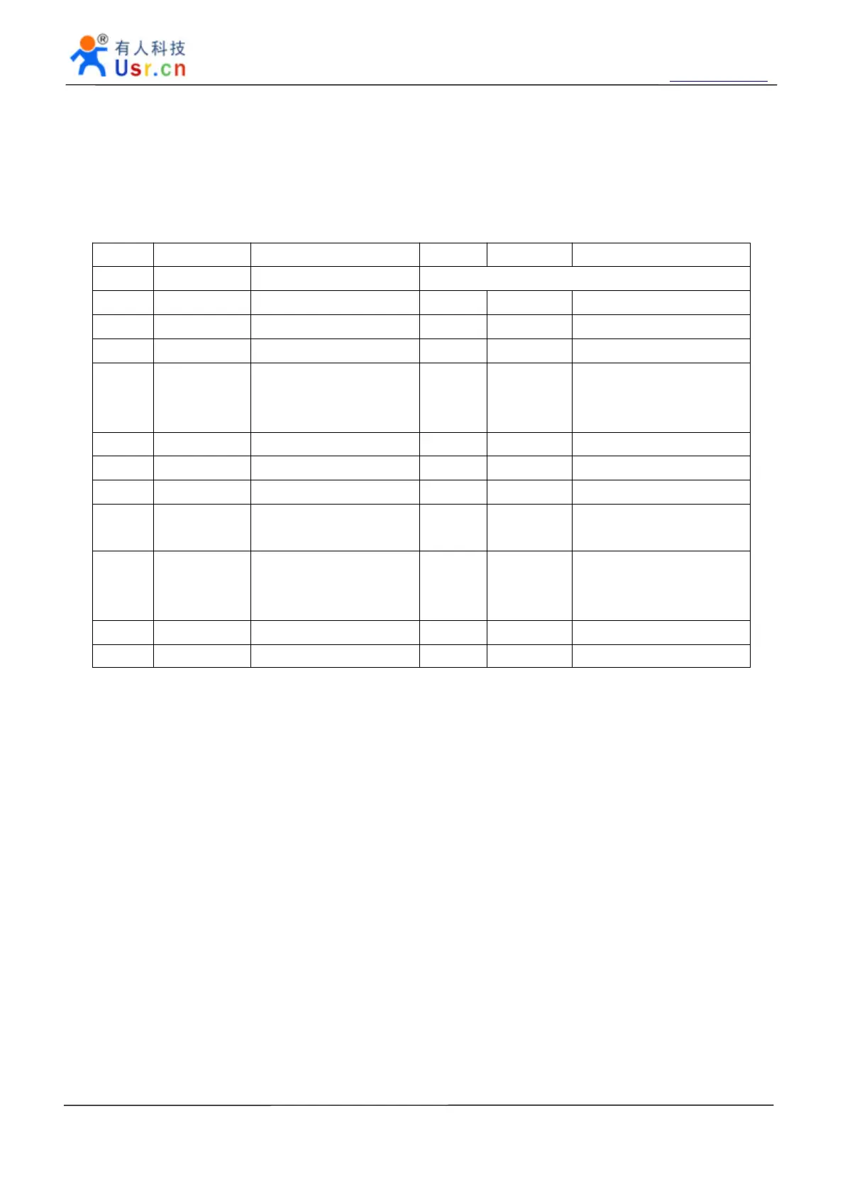
Pin Name Description Pin Name Description
1 TX+ Transceiver Data+
A
breach here
2 TX- Transceiver Data- 23 NC
3 RX+
To
RJ45 Pin3 22 NC
4 RX-
To
RJ45 Pin6 21 NC
5 Data_LED Link to yellow Led and
through a resistance to
VCC
20 NC
6 TXD Transmit data 19 NC
7 RXD Receive data 18 ISP For Update
8 RTS RS485 enable pin 17 NC
9 CFG Config enable port for
RS232 Config
16 3.3V DC3.3V input and5V use
1 is ok.
10 RST Reset pin, 200ms low
for reset
15 LINK Link to green Led and
Through a resistance to
VCC
11
GND
To
GND 14 5V DC5V input @200mA
12 GND
To
GND 13 5V DC5V input @200mA
2.3.22
2.3.22
2.3.22
2.3.22 LED
LED
LED
LED status
status
status
status
USR-TCP232-D Red LED, If the indicator is energized, the module power input is correct .
 Loading...