S erial to Ethernet module USR-TCP232-T24 series http://en.usr.cn
Jinan USR IOT Technology Limited Page 30 of 53 tec@usr.cn
3
3
3
3 .
.
.
. Work
Work
Work
Work Mode
Mode
Mode
Mode
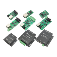
3.1
3.1
3.1
3.1 Block
Block
Block
Block diagram
diagram
diagram
diagram
Serial to Ethernet
Converter
Ethernet
power
User
device
TTL
Take
Take
Take
Take USR-TCP232-T
USR-TCP232-T
USR-TCP232-T
USR-TCP232-T for
for
for
for example,
example,
example,
example, show
show
show
show demo
demo
demo
demo application
application
application
application of
of
of
of module
module
module
module USR-TCP232-T
USR-TCP232-T
USR-TCP232-T
USR-TCP232-T
3.
3.
3.
3. 2
2
2
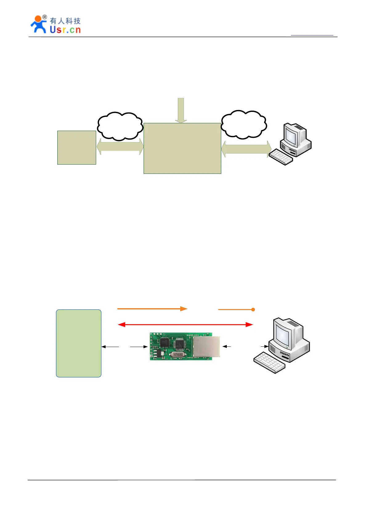
2 TCP
TCP
TCP
TCP Client
Client
Client
Client Mode
Mode
Mode
Mode
In TCP client mode, after power on module according to their own Settings active TCP server to connect
to the server, and then establish a long connection, data transparent transmission after this mode, the TCP
server IP module would need to be visible and the visible means directly by module's IP can PING the server
IP,
server side can be fixed
IP,
the Internet can also be internal network IP and module in the same local area
network .
MCU
51
51
51
51
,
,
,
,
AVR
AVR
AVR
AVR
,
,
,
,
PIC
PIC
PIC
PIC
,
,
,
,
ARM
ARM
ARM
ARM
COM
Ethernet
1
.
Module try to connect to server
2
.
Data transfer through the connection
1 . Server listen a TCP port
Module work at TCP Client mode
3.3
3.3
3.3
3.3 UDP
UDP
UDP
UDP mode
mode
mode
mode
In UDP mode, after the module is powered on listening on port Settings, not take the initiative to
establish a connection, when data from by forwarding to the serial port, when a serial port receives the data
sent over the network to the IP and port module Settings .
 Loading...