FLW2446N_SVG
HOT
COLD
9
8
7
4
3
2
1
5
6
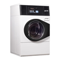
1. Faucet
2. Fill Hoses
3. Install this end of hose to valve connections at rear of
washer
4. Plain Rubber Washer
5. Cold Water Connection
6. Hot Water Connection
7. Install this end of hose to water supply faucet (Black col-
ored or hex nut shaped coupling for BSPP thread)
NOTE: Both couplings on fill hoses included with
models starting Serial Nos. beginning 1810 are
BSPP thread.
8. Filter Screens
9. Double Check Valves (model numbers ending in "06"
through Serial No. 1909999999)
Figure 7
IMPORTANT:
Hoses and other rubber parts deteriorate after exten-
ded use. Hoses may develop cracks, blisters or materi-
al wear from the temperature and constant high pres-
sure they are subjected to.
All hoses should be checked on a monthly basis for
any visible signs of deterioration. Any hose showing
the signs of deterioration listed above should be re-
placed immediately. All hoses should be replaced ev-
ery five years.
IMPORT
ANT: Turn off water supply faucets after check-
out and demonstration. Owner should turn off water
supply whenever there will be an extended period of
non-use.
Install Appropriate Electrical Cord –
Washers Equipped W
ith Heater
230 Volt, 50 Hertz, 21 Amp, Single-Phase
NOTE: This washer is factory-wired for a 230 Volt, Sin-
gle-Phase electrical supply.
Have a qualified electrician install appropriate electrical recepta-
cle.
To attach customer
-supplied power cord:
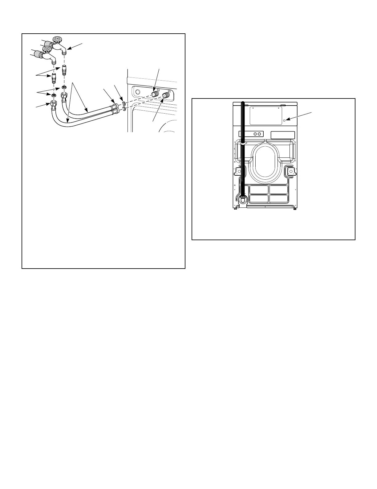
1. Remove electrical access panel on rear of machine.
2. Remove plastic plug from hole in rear of machine.
3. Install strain relief, supplied with machine, in hole.
4. Put power cord through hole.
1. Install power cord through this hole after removing plastic
plug. Use strain relief supplied in accessories bag.
Figure 8
5. Attach power cord wires as shown in Figure 9 .
6. Tighten down the strain relief (supplied with unit) on the
power cord.
7. Reinstall access panel.
Installation
©
Published by permission of the copyright owner -
DO NOT COPY or TRANSMIT
13 Part No. 805412R7