SECTION 3 - CHASSIS, PLATFORM & SCISSOR ARMS
3-4 – JLG Lift – 3121642
REMOVAL:
SHUT MACHINE OFF, BRACE AXLES AND CHALK WHEELS TO PREVENT
MACHINE FROM MOVING DURING REPAIRS.
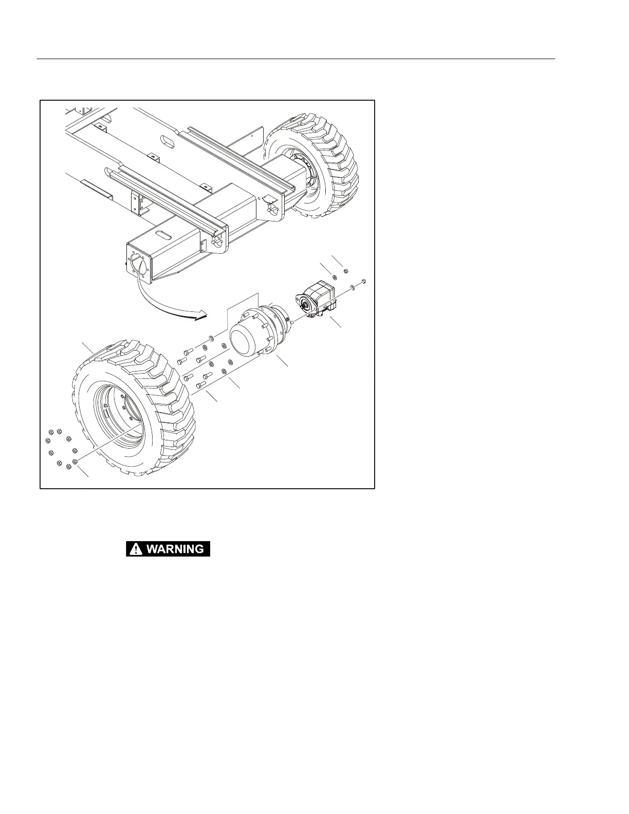
1. Disconnect, cap and label all hydraulic lines attached to
Drive Motor (6). If applicable, disconnect all electrical
wiring.
2. With axle raised and supported, remove the Tires (1)
from the Drive Hub (3) by removing the 9 Lugnuts (2).
3. Remove the Drive Hub (3) and Drive Motor (6) from the
axle by removing the 6 Bolts (4) and Washers (5).
4. The Drive Motor (6) can be removed from the Drive Hub
(3) by removing the 2 Nuts (7) and Washers (8).
INSTALLATION:
1. Follow "Removal" procedures in reverse order.
2. Refer to Table 3-1, Wheel Torque Chart when torqueing
Lugnuts (2).
NOTE: For detailed information on the Drive Hub and Drive
Motor, refer to Section 3.3, Drive Hub (Fairfield) and Section
3.4, Drive Motor (Sauer).
1. Tire & Rim
2. Lugnuts
3. Drive Hub (Fairfield)
4. Bolt, 5/8"-11NC x 1 3/4"
5. Hardened Washer, 5/8"
6. Drive Motor (Sauer)
7. Nut, 1/2"-13NC
8. Hardened Washer, 1/2"
NOTE: Rear Axle Shown
Figure 3-2. Drive Assembly - (Fairfield/Sauer)