13
Joerns® Bed Frames
EasyCare®
©2023 Joerns Healthcare • 6110444 RevA • 000547
1 2 3
6
5
4
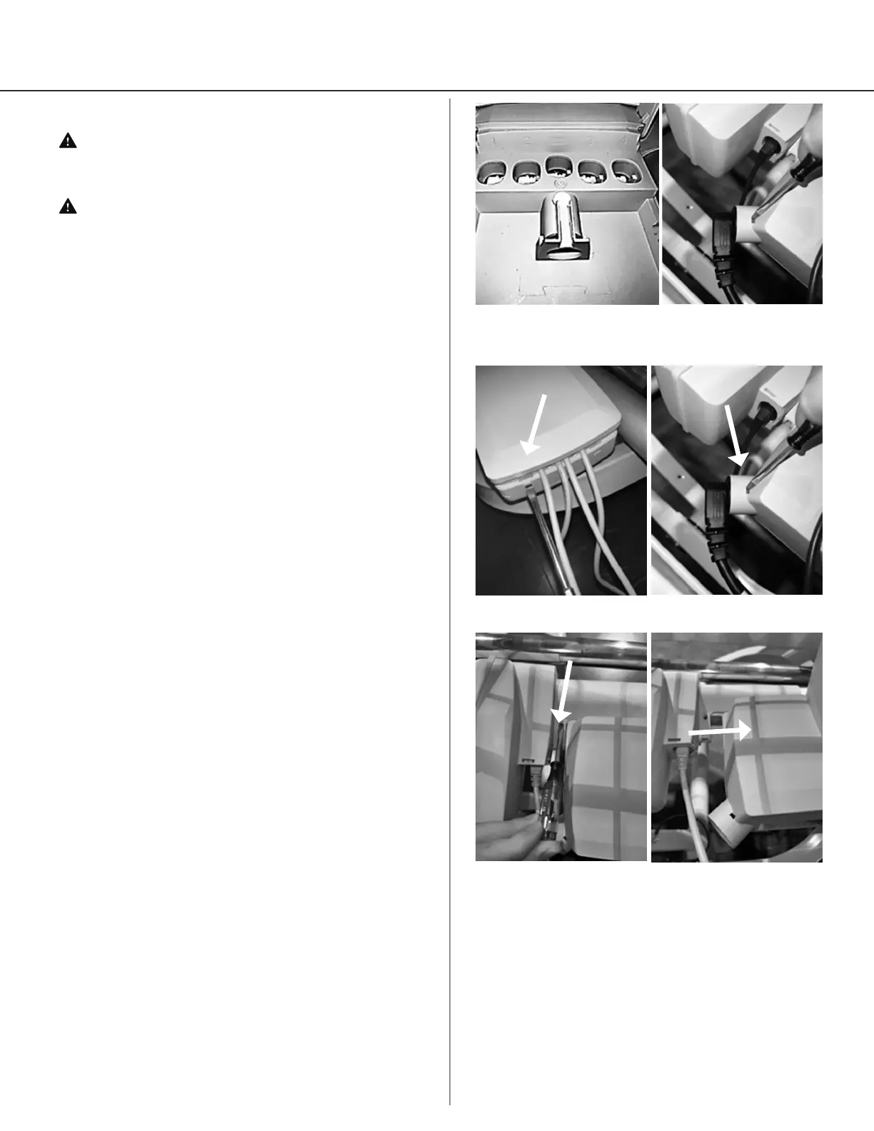
Figure 30 Figure 31
7
Actuator and Control Box Information
Warning: Possible Shock Hazard. Unplug the
power cord from the wall outlet before performing any
maintenance/service to the control box.
Warning: Possible High Temperature. Prior to
servicing any electrical component ensure the
component has cooled to room temperature.
Note: Overload protection is achieved via current
sensing technology, which will reset automatically if
any bed function fails to operate. Ensure that the bed
is not overloaded or constrained from movement.
Actuator And Control Box Identication
Cable and Port Identication (Figure 30 and Figure 31)
1. Head Leg Hi/Low Actuator - drives head leg (Port 1)
2. Back Actuator (Port 2)
3. Foot Leg Hi/Low Actuator - drives foot leg (Port 3)
4. Knee Actuator (Port 4)
5. Control Harness (Center horizontal port)
6. Battery Accessory (Port w/ battery symbol)
7. AC Power
Note: The actuators and control box contain no
serviceable parts. Overload protection is achieved via
current sensing technology, which will automatically
reset. If any bed function fails to operate, check to see if
the bed is overloaded or constrained from movement.
To Remove Control Box
1. Plugs and outlets are numbered so they can be
easily reinstalled later (See Actuator And Control
Box Identication).
2. Unplug from wall outlet.
3. Elevate the knee section of the sleep deck to ease
the removal of the control box.
4. Open the cable cover from the control box using
the small at screwdriver to pry both locking tabs
free at both ends (Figure 32). Unplug the actuator
cables and the pendant or sta control cable.
5. Remove the main power cord by pressing in the
red tabs on both sides of the housing with the
small at screwdriver and pulling the plug out of
the housing (Figure 33).
6. If installed remove battery patch cable from
control box
7. Using the small at screwdriver, detach the control
box from mounting bracket connected to the
Hi-Lo actuator by pressing the internal tab gently
inwards (Figure 34).
8. Now the control box can be separated from the
actuator by sliding it o the actuator’s mounting
bracket connected to the Hi-Lo actuator housing
(Figure 35).
9. To replace the control box, reverse these instructions.
Figure 32 Figure 33
Figure 34 Figure 35
 Loading...