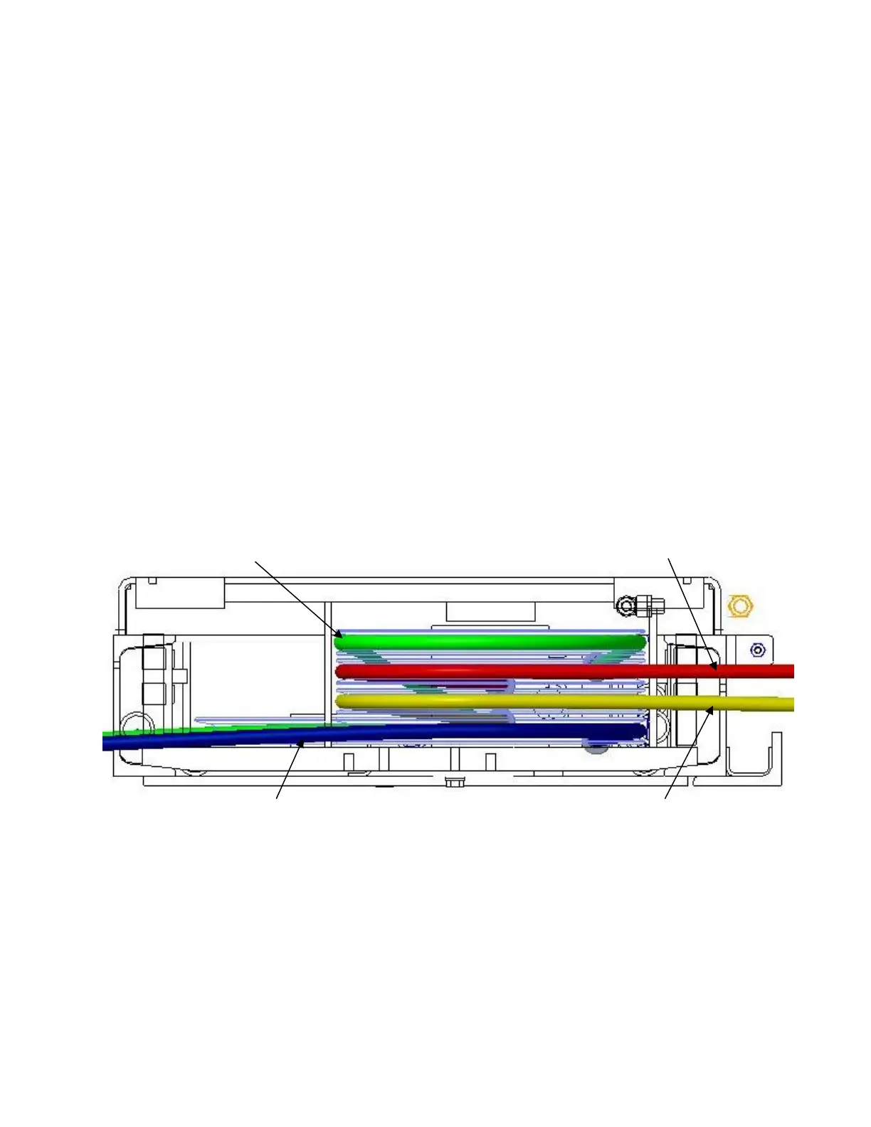
Route cable #1 through the idler runway, into the front cross beam access hole, and out
the right end of the front beam. (Don’t forget to route it up over the cross-braces in the
bottom of the runway.), Figure 9.
Route left front cable #2 through the access hole and up out the left end of the front
beam, Figure 9.
Re-install the cross-beam pulleys with one plastic bearing washer on each side of each
pulley.
Re-install the idler runway pulleys, with one plastic bearing above and below each
pulley per Figures 7 & 8. Note: use one 2 1/8” long spacer at the idler rear pulley only.
Confirm that a 2 1/8” spacer is installed at the rear of the idler runway and none at the
front of power or idler runways.
Attach both cross beams to the runways (Figure 7) with M12 x 35mm lg. flange head
bolts (two at each end of each runway) being careful not to pinch the air line. Leave the
poly tubes hanging out the bottom of the cross-beam access holes at this time, they will
be fed in through the runway after the lift is raised. The outermost power runway
slots should be in line with the outermost holes in the top of the cross beam. The
idler runway can be installed using the outer or inner sets of cross beam holes, see
“Width Between Runways” dimension in Page 6. Do not torque bolts yet.
Check the layout of the lift in the bay. (This is the last opportunity to re-position the lift.)
Adjust the position of the runways so the distance from power side jack rail to idler side
jack rail is the same at the front and the rear and the diagonal measurements from the
front tip of one rail to rear tip of the opposite rail are within 1/4”, Figure 9.
Center cross beam bolts with slots in runway and tighten. (Be careful not to move
runways.)