Identify and place coiled cables as follows, close to their respective towers (Table 1):
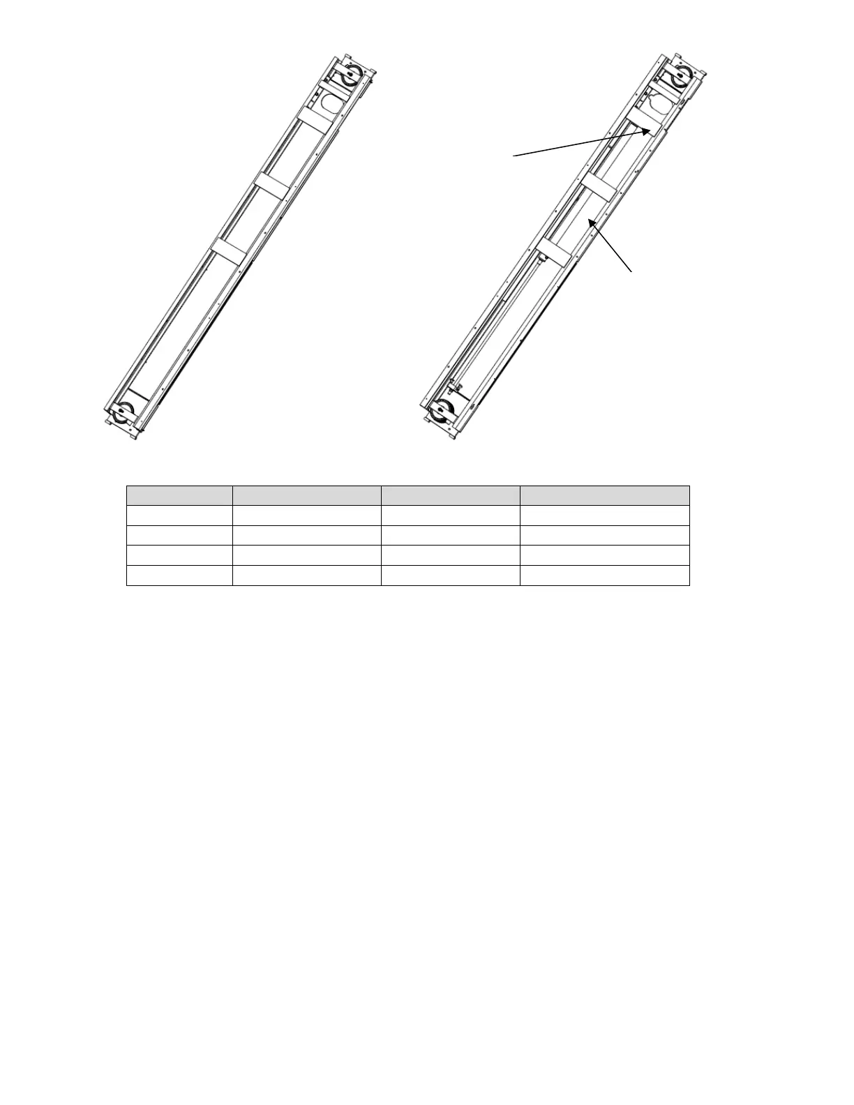
All cables are pre-install in L.S. Runway, see Figure 5
Table 1: Cable part numbers
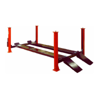
7.3 CROSS-BEAMS AND RUNWAY ASSEMBLIES
Unpack lift. Remove all packaging from Power Runway (power runway has four cable
pulleys at rear end) and pull threaded cable ends out. Make sure the cables are in the
proper pulleys at the 4-stack, Figure 5
Position runways on blocking (see Figure 6) per layout lines established as Figure 2 &
3. Use four 30” long 4x4’s spanning the width of the runway and four 12” long 1x4’s to
shim up the jack rail side of the runway. Cable #1, #3, & #4 should be extending out
from the rear of the power runway and cable #2 from the front of the power runway.
Position the front and rear cross beams, Figure 6. (Front Cross beam are marked with
FRONT label on the parts.)
Remove the four (4) cross beam pulleys (one pulley from each end) and the two idler
runway pulleys (also one pulley from each end). The runway pulley pins do not need to
be removed, just lowered enough to remove the pulleys, Figure 10.
Starting from the bottom of the pulley stack, route cable #4 through the access hole and
up out the left end of the rear beam. Repeat for cable #3 out the right end of the rear
beam. Route cable #1 through the access hole, and back out the idler side access
hole. Look through the idler end of the cross beam and ensure that cable #1 and
#3 have not crossed, Figure 9.
HYDRAULIC CYLINDER
MOUNT PLATE