7.4 COLUMN INSTALLATION
Stand up a column assembly near each corner of the lift (column with power unit
bracket goes at the front left corner, power front) and check the locking ladder bar
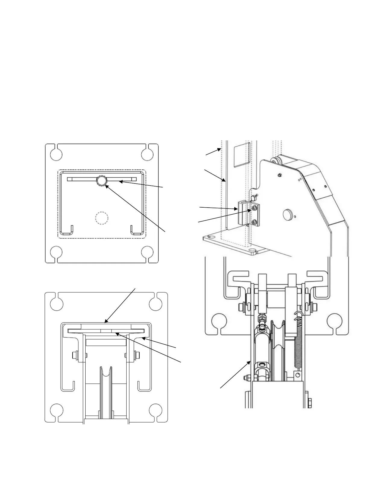
orientation per Figure 11. Note that the center of the threaded rod is offset (away from
the back of the column) from the center of the ladder. Thread the locking ladder jam nut
(located under the column top plate) down approximately 6” to allow the ladder to be
lifted freely.
Slide power side column onto cross beam until the M8 threaded holes in the side of the
beam are just exposed. Position slide blocks as shown in Figure 12 and attach with M8
x 16mm lg. bolts (apply thread locking compound before installing).
Raise the locking ladder, push the column against the slide blocks, and lower the ladder
into the slide blocks, Figure 13.
Figure 13 – Locking Ladder Orientation
Figure 11 – Locking
Ladder Orientation
Figure12 – Slide
Block Installation