JOHNSON CONTROLS
11
SECTION 2 - CONNECTING BAS TO A SERIES 100/YPAL UNIT WITH THE IPU CONTROLLER
FORM 100.50-SU8
ISSUE DATE:1/28/2016
2
LON
• To communicate to a BAS utilizing LON proto-
col, a JCI E-Link must be used
a. YK-ELNK101-0
b. YK-ELNKE01-1 (with enclosure)
• The wires from the E-Link to the IPU controller
will be connected to Port 1 (See Figure 1 on page
10)
• P1 Protocol set to BACnet. See above under
BACnet MS/TP to locate P1 Protocol in the Ser-
vice Menu
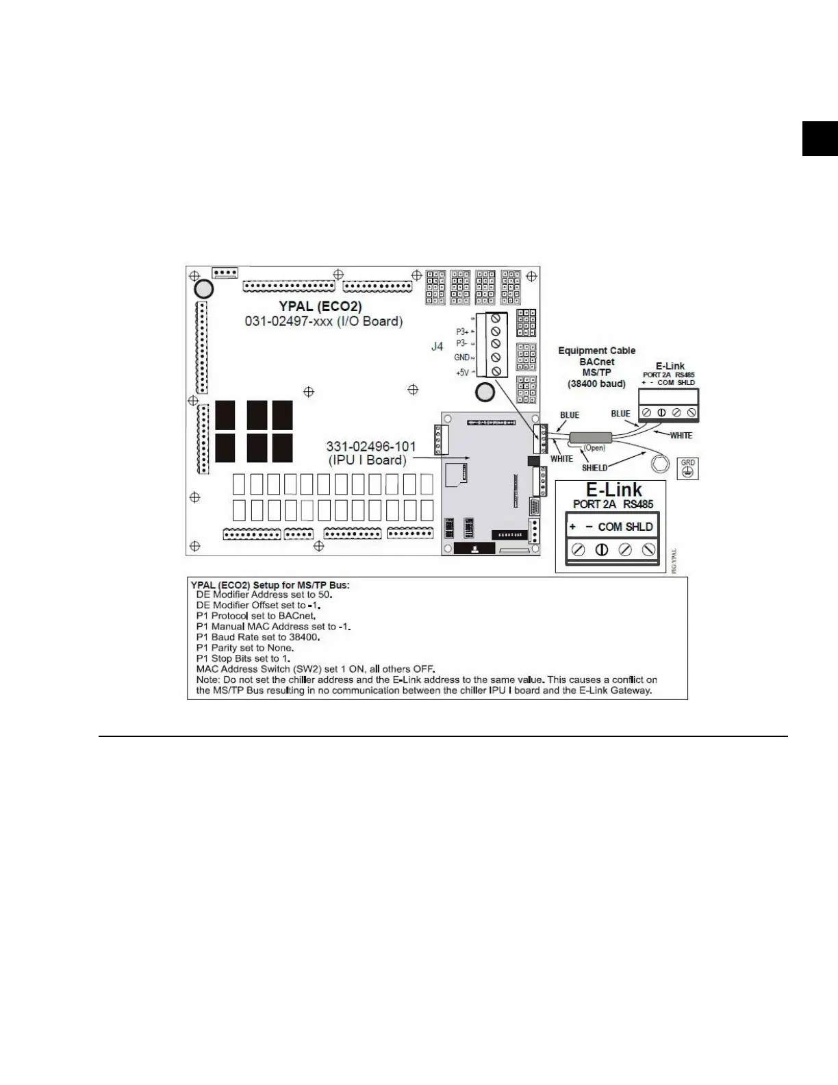
See Figure 2 on page 11 for addressing the E-Link
to the IPU Controller.
FIGURE 2 - E-LINK CONNECTIONS AND ADDRESSING INSTRUCTIONS
N2
• To communicate to a BAS utilizing N2, a JCI E-
Link must be used
a. YK-ELNK100-0
b. YK-ELNKE00-0 (with enclosure)
• The wires from the E-Link to the IPU controller
will be connected to Port 1 (See Figure 1)
• P1 Protocol set to BACnet. See above under
BACnet MS/TP to locate P1 Protocol in the Ser-
vice Menu
See Figure 2 on page 11 for addressing the E-Link
to the IPU Controller
OTHER PROTOCOLS
• The IPU controller is also capable of communi-
cating with other BAS protocols
a. MODBUS Server
b. MODBUS Client
c. MODBUS I/O
d. Terminal
e. API

 Loading...


