689670-BIM-A-0311
50 Johnson Controls Unitary Products
Adjustment Of Temperature Rise
The temperature rise (the difference of temperature between the
return air and the heated air from the furnace) must lie within the
range shown on the CSA rating plate and the data in Table 9.
After the temperature rise has been determined, the CFM can
be calculated as follows:
After about 20 minutes of operation, determine the furnace
temperature rise. Take readings of both the return air and the
heated air in the ducts (about 6 feet from the furnace) where
they will not be affected by radiant heat. Increase the blower
CFM to decrease the temperature rise; decrease the blower
CFM to increase the rise (See SUPPLY AIR DRIVE
ADJUSTMENT).
NOTE: Each gas heat exchanger size has a minimum
allowable CFM. Below this CFM, the limit will open.
Burners/Orifices Inspection/Servicing
Before checking or changing burners, pilot or orifices, CLOSE
MAIN MANUAL SHUT-OFF VALVE AND SHUT OFF ALL
POWER TO THE UNIT.
1. Open the union fitting just upstream of the unit gas valve
and downstream from the main manual shut-off valve in
the gas supply line.
2. Remove the screws holding each end of the manifold to the
manifold supports.
3. Disconnect wiring to the gas valves and spark igniter(s).
Remove the manifold & gas valve assembly. Orifices can
now be inspected and/or replaced.
To service burners, complete step 4.
4. Remove the heat shield on top of the manifold supports.
Burners are now accessible for inspection and/or
replacement.
NOTE: Reverse the above procedure to replace the
assemblies.
Make sure that burners are level and seat at the rear of the gas
orifice.
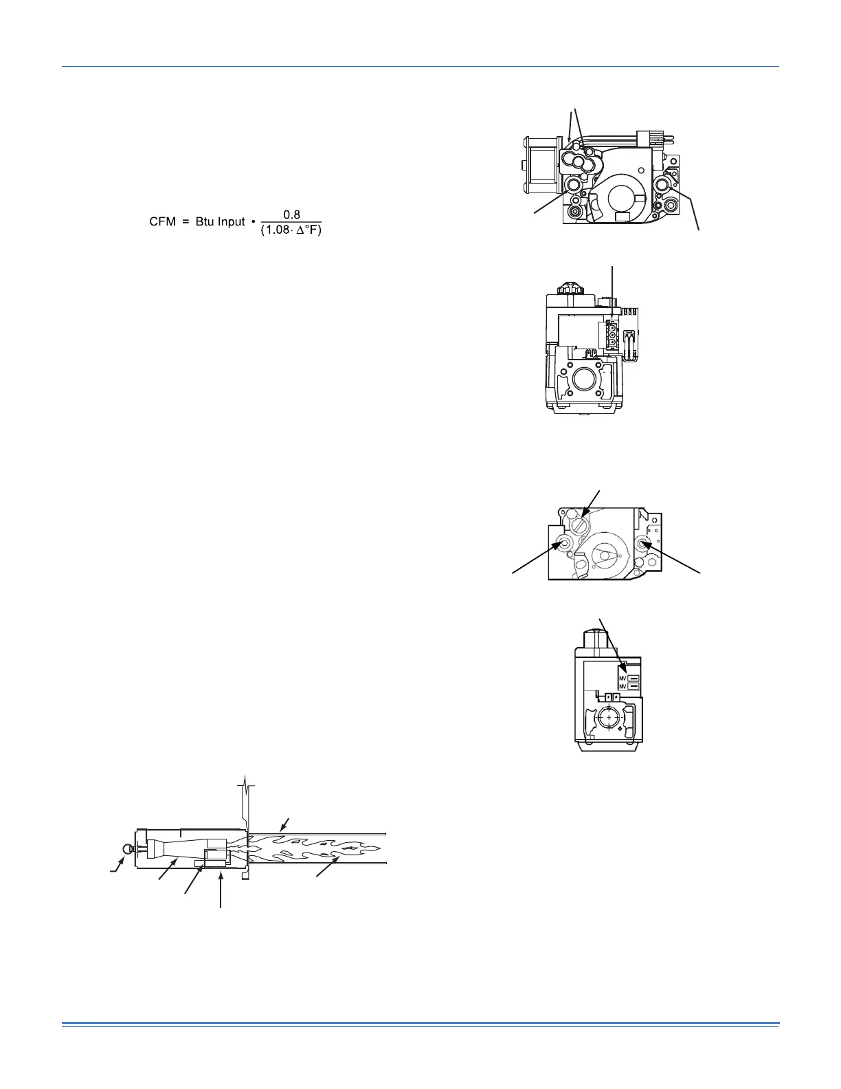
Figure 29: Typical Flame
Figure 30: Typical Two Stage Gas Valve
Figure 31: Typical Single Stage Gas Valve
Charging The Unit
All ZU units use Thermal Expansion Devices. Charge the unit to
10° subcooling.
HEAT EXCHANGER TUBE
BURNER FLAME
(BLUE ONLY)
IGNITOR
BURNER BRACKET
BURNER
GAS
SUPPLY
PIPE
INLET
PRESSURE
TAP
HIGH & LOW GAS ADJUSTMENT
OUTLET
PRESSURE
TAP
MATE-N-LOCK
CONNECTORS
HI
LO
ON
OFF
MV
C
HI
INLET
PRESSURE
TAP
OUTLET
PRESSURE
TAP
GAS
ADJUSTMENT
ELECTRICAL
TERMINALS
 Loading...